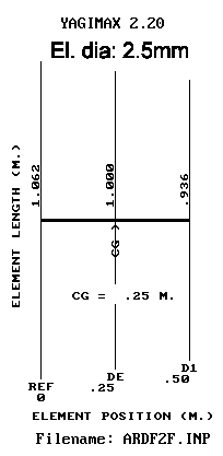
3el. yagi : dimensions
!! el. dia 2,5mm !!
|
A very effective, light weight, short and sturdy 3 el. 145MHz direction finding antenna. |
An ARDF- (radio foxhunt) antenna has to be designed to the following criteria:
1. Has a very good Front/Back ratio
2. Exact known minima
3. Little or no side lobes
4. Is very sturdy
5. Lightweight
6. And easy to handle
The antenna described here is developed and tested with these objects in mind. After some theoretical antenna experiments, a total length of only 50cm was chosen for easy handling.
ARDF-foxhunting often means: fast running in accidental terrain, sometimes probing through bushes. So a foxhunt antenna must be sturdy. When starting, i listen first for max. signal to decide in which direction roughly to go (using the good F/B). Then, while running, i listen if the signal is becoming stronger, and in which direction the other foxes are (cross-bearings). So the directivity must be good. In other words: the antenna may not have side lobes and the front/back ratio must be very good.
When being very near the fox to find, and the fox comes in the air, i first quickly determine with a max. bearing in which direction to go. Then, while fast running towards the fox, i take constantly the more exact minimum-bearings to pinpoint and find it. Even when the fox is silent again, i can sometimes find it following the last exact minimum-bearing.
The sometimes used HB9CV antenna is a small antenna, but mostly asymmetrical in electrical construction. It therefore suffers from skewing and Asymmetrical minima at the back, and a limited front/back ratio. It also has a wide front lobe. Therefore i cannot make an accurate bearing with it.
The electrical design with YAGIMAX 2.2.
Why designing with the use of a computer:
It is difficult, expensive and time consuming to experiment with real antenna-prototypes. Reliable measurements of the radiation-pattern (Front-Back ratio) are difficult. But a
suitable computer program designs and calculates this in minutes. Then ask the program to optimize the wanted property, and compare the result with earlier design stages. For the
radio amateur, antenna "experiments" made with a computer-program are fast and fun, more reliable (i think), and less expensive. And the computer is really used for HF
experiments.
Three or more elements?
In wet forests and in mountain-terrain it could be an advantage to have a smaller beam width. With 4-element antennas, smaller beam width could be obtained, or a bit better
F/B. But a 4-el. will be longer and heavier, thus less easy to handle. Therefore i
sticked to the 3-el. design, as good F/B and handling is important.
Just for fun, i designed a 4 element yagi, starting from a 10 element long-yagi from DL0WU. It is used in the frequency-range, where F/B is maximal, with the dipole tuned for resonance. It has 10mm diameter elements. You find it at the end of this article, to compare it with the three element version, which has 2.5 mm diameter elements.
Insulated elements.
Observe that this design is made for director and reflector insulated from the boom. When using a metal boom, all elements must be isolated from it. When the director
and reflector are making contact with a metal boom, they must somewhat be lengthened. When you should use a different element-diameter, you must correct the element-lengths too!
Use a antenna program or a table in a handbook to calculate.
|
|
|
3el. yagi : dimensions |
Which program?
I used YAGICAD 4.1 from VK3DIP at first. The prototype antenna was looking ugly (a wooden bar with some thin spring steel rods through it) but it worked at once when measured at an
antenna-measuring day! This was encouraging. I used two different practical copies for two years.
I checked the results with another antenna-design program, YAGIMAX 2.20 from K4VX. The results were comparable, but YAGIMAX seemed to give results shifted about 1.5 MHz down in frequency for the same antenna design. For this article, i checked both programs with several designs with known properties. I concluded, that it was YAGICAD which gave results shifted to a higher frequency. With YAGIMAX, among other designs, a 10 el. long yagi for instance from DL6WU gave nearly exactly correct results (E-plane plot and VSWR over 10 MHZ BW) compared with the published results from measurements.
So i designed a new 3el. yagi with YAGIMAX, optimizing again for F/B, and checking it with YAGICAD. YAGICAD gave again results shifted abt 1.4 MHZ upwards,
like with other antenna designs of know properties before. I think, YAGIMAX is right.
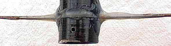
Construction details.
A practical model is made from sturdy, light weight materials. The boom is 30mm fishing-rod. Elements where made from 2.5 mm spring-steel rod,
obtained from a model-builders shop. You easily can tin-solder the steel rod to pieces of copper clad, easing construction. This material can be bend almost 90 degr. without
deformation or breaking, but is in practical use stiff enough. This adds to the ruggedness and is handy when going through bushes and making a bearing under windy conditions.
In practice this thin rod is better then the use of steel measuring-tape, which collapses in the wind, and of which the electrical shortening-factor is unknown. And in interest of
easy copying the design, how can i know for sure, what the exact element-resonance then are? After all, this is the most critical point of an antenna.
The dipole is located in the middle between the director and the reflector. Antenna length is 1/4 lambda (0.5 m). Experiments showed that the feedpoint-impedance then is not
to low, combined with good F/B and bandwidth (see also the 4 element design).
Do NOT use protecting shells or eyes on the ends of the elements, as they DETUNE the elements, even when made
from an insulating material !! Keep elements straight and even in thickness.
(see below if you want eyes).
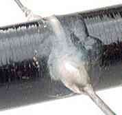 In the prototype, i sawed a 3mm wide slit in the boom for the director, to the middle of the boom. Centered the director in
it, fastened the rod and filled the gap with a thermal glue pistol. Use carefully a blowtorch to let the glue flow firmly to the rod and the boom.
In the prototype, i sawed a 3mm wide slit in the boom for the director, to the middle of the boom. Centered the director in
it, fastened the rod and filled the gap with a thermal glue pistol. Use carefully a blowtorch to let the glue flow firmly to the rod and the boom.
The reflector could not be made out of one piece, as the rods were purchased in lengths of 100cm. I did cut the reflector in two
halves, and soldered them on a small piece of copper clad. Then sawed a slit of about 4mm in the boom and glued the reflector in place like the director.
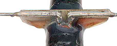 The dipole was also made out of two halves. The dipole has a gap of 10mm in the center
for the feed point. The short feed point ends of the dipole were bended 90 degr. down, and soldered on a trapezium-shaped piece of copper clad, which had two copper surfaces to
solder the rods on (see photo). For isolation the copper was filed away in the middle between them.
The dipole was also made out of two halves. The dipole has a gap of 10mm in the center
for the feed point. The short feed point ends of the dipole were bended 90 degr. down, and soldered on a trapezium-shaped piece of copper clad, which had two copper surfaces to
solder the rods on (see photo). For isolation the copper was filed away in the middle between them.
The dipole is electrically balanced to the coax cable by a transformer with a winding-ratio of 2:2 or 2:3 (ant - coax). The two-hole ferrite core must be suitable for VHF-transformer use (Philips: 4B1, length 8mm, width 8.5mm). Run the windings over the mid-leg of the core.
Measure the length of each dipole-half on the straight part between the feed point-end and the end of the element-half. The ends bended down to the transformer are not part of the dipole, but part of the feed line.
Another balancing-device between the coax and the dipole could be used of course. It can prevent possible losses in the transformer. But the isolation between the coax-outside and the dipole must be good, as the antenna will "skew" when balancing is not perfect. This causes difficulties during competition (running in a spiral around the fox, HI). A DELTA-mach transforming to 200 ohms could work well, but is mechanically vulnerable. You still need a balancing device, like a 1/2 wave coax-loop (see antenna-handbooks). A Gamma-match can give directly 50 ohms asymmetrical impedance, but is mechanically asymmetrical. Maybe this can cause "skewing" too.
After soldering the ferrite transformer with coax to the dipole, the whole was water protected by covering all connections with thermal glue. This adds to the strength of the dipole! Then a slit was sawed in the boom, and a hole filed to let pass the transformer with the cable. The dipole/transformer/cable were slipped in the boom, and glued to the boom firmly. The cable runs through the boom to the receiver. It can help when glue is applied and flowed to the boom before putting the dipole in it. Be sure that all elements are exactly in parallel. Warm the glue with an blowtorch and reposition an element when soft.
Handling. Building together with the receiver.
|
I installed my receiver behind the reflector, with enough room for my hand between the receiver and reflector. My body then cannot influence the radiation-diagram of the antenna. |
The center of gravity is where my hand is on the boom, and the whole combination is balanced in my hand, easing handling.
A fast and accurate minimum bearing on a horizontally polarized signal can easily be done, by pointing the antenna to the sky. Turn the antenna with the boom as axis. This way you are using only the dipole for reception, and ground reflection is suppressed due to the vertical directivity of the antenna. The minimum in signal then is very sharp and accurate!
The graphs. Element diameter: 2.5mm.
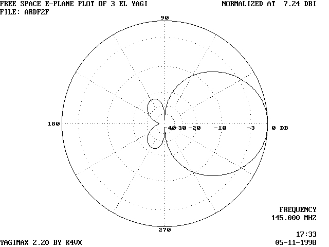
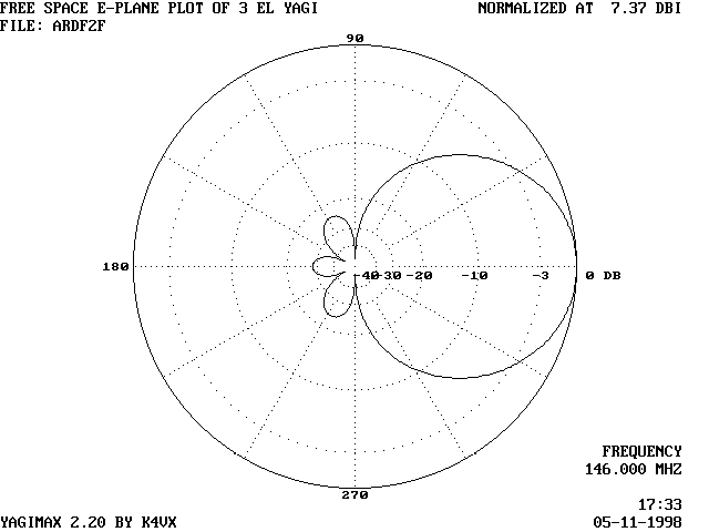
3el yagi : hor. diagram @ 145MHz
The Front to Back ratio (F/B) in this graph means the suppression of the signal when the antenna is pointing exactly with his back (180) to the transmitter.
This antenna showed over 20dB suppression of the signal over an angle of more than 180 degrees. And also in practice when building
several more. This is an excellent property for foxhunting!
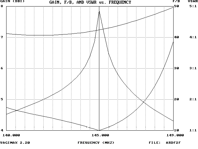
3 el. yagi : Gain-F/B-VSWR graph.
The lower curve indicates the VSWR. The upper curve indicates the theoretical antenna gain in DBi.
In this graph, the sharp peak in the middle curve means, that the F/B ratio theoretically is at his best at exact the center frequency where the antenna is tuned to. At that frequency there is a very deep and sharp null at exactly the back of the antenna.
The practical deepness and direction of the null at the back depends on the construction details of the antenna, f.i if the feed line is really balanced to the radiator element. When HF on the outside of the screening of the coax is not blocked from the antenna, it will be coupled to the radiator and then to the inside of the transmission cable. It then influences the radiation pattern of the antenna. Balancing and decoupling the outside of the coax therefore is very important.
So, in practice this null cannot be used to take an accurate null-bearing, only to null-out an unwanted signal. A good null-bearing can be made, by pointing the antenna vertically (to the sky), and turning it, using the boom as vertical axis. When you hear the very sharp minimum in signal, the radiator is pointing to the signal source. This works even better than with a bare dipole, as ground reflections ar suppressed by the directivity of the antenna.
The bandwidth for 20dB FB is -3Mhz +2,25 MHz. When, due to construction errors ALL elements are 1% to short or to long, the center frequency of the antenna shifts about 1.5 MHz up or down. The F/B then will be still 20dB or more. This indicates the good properties of this design for home-building the antenna with good results.
After assembling of the antenna, do NOT bent eyes or put insulating pieces of rubber or plasic on the ends of the elements.
Due to the extra capacitance the introduce, all elements will be detuned, and it is impossible to predict what the resonant frequency of the
elements and the performance of the whole antenna wil be! The good properties of the designs will be destroyed.
How to make eye protection on the element-ends.
If you want protection on the element ends, first make a test element. BEFORE you make and install the antenna elemens.
Support a test element of exact 1m long on a string in the middle of the element.
Measure the resonant frequency using a dip meter.
Bend bot element ends into a closed circle with inner diameter of 10mm.
OR
Solder small metal balls on both ends
OR
Glue plastic feet on both ends.
Measure again the resonant frequency.
Calculate the percentage in which both resonant frequencies differ ( + or -).
Before bending/soldering/gluing the actual antenna element ends, the length of all raw (still not bend) elements must change according that calculated percentage frequency change.
This length change compensates for the extra dimensions and the extra end-capacitance of the protectors.
REM: a freqency difference of plus X percent means a length difference of minus X percent and vice-versa.
Install the protection on the element ends.
Results.
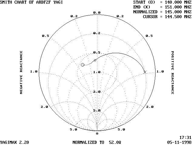
3el. yagi : Z-plot.
I checked the predicted behavior in the wanted frequency-range with polar plots on the band-edges at 144 and 146 MHz (E = looking on top of the antenna, like the antenna-drawing above).
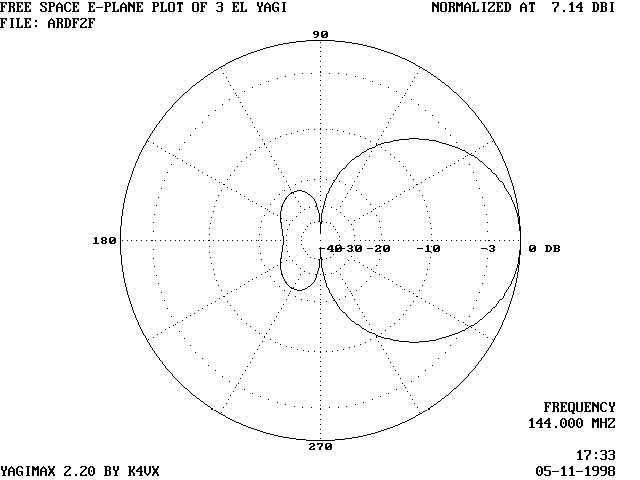
3 el. yagi : directional plot @ 144 MHz.
3el. yagi, directional plot @ 146 MHz
These plots indicate, that the design is not to critical. When the elements are ALL shortened or lengthened a bit, due to metal contact with the boom, or a thicker center-part (detachable elements), it is not disastrous to the F/B. It is difficult to measure the real properties of the antenna in the field, so this is my way to be sure, the antenna is reproducible.
Four element yagi. Element diameter: 10mm.
Another design for a four element yagi with very good F/B, wide
bandwidth and reasonable impedance. Length: 0.94m.
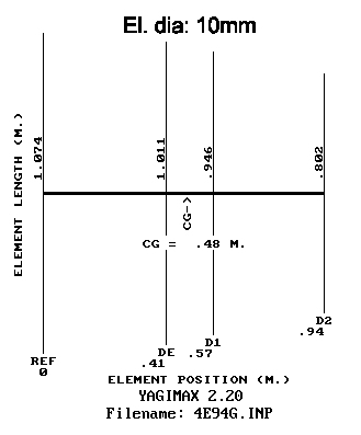
4 el. yagi : dimensions.
!! element dia 10mm (curtain rod) !!
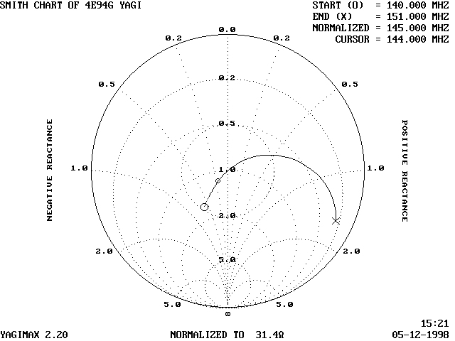
4 el. yagi : Z-plot.
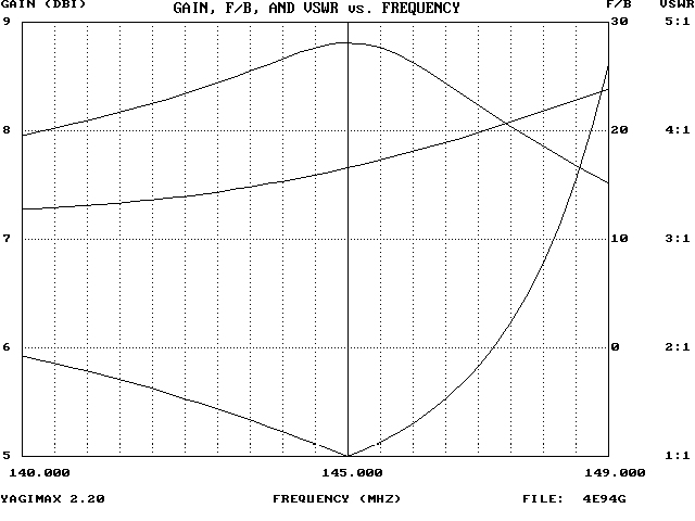
4el. yagi : gain-F/B-VSWR plot.
In this 4 element design (10mm elements), the 20dB F/B bandwidth is even greater: -4,5 / +2,5 MHz. From the graphs below can be seen, that at +-1MHz the F/B is more then 25dB over an angle of about 200 degrees.
The design can be scaled, when using other element diameters or other center frequency. All elements then have to be shorter or longer by the same amount.

4el. yagi : directional plot @ 145MHz.
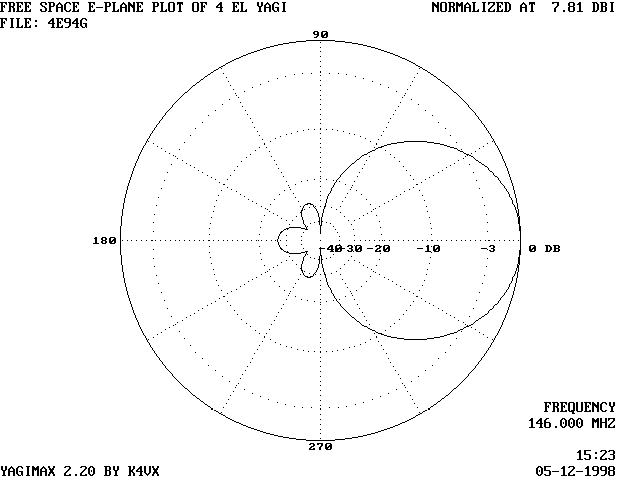
4el. yagi : directional plot @ 146MHz.