|
<< |
DIY blanc PCB set
for
Pa0nhc improved version of
pa0rdt "Miniwhip" active wideband receiving antenna.
NOW FIRST press F5 to update this page to its
newest version !
Update : 20201223 / 20240203 (Layout and BF998).
20240215 (ant properties).
First see my
Youtube
presentation of The Miniwhip. |
(C)
The use, copy and modification of all info on this site
is permitted, but only for non-commercial
purposes, and
thereby explicitly stating my radio amateur call sign "PA0NHC"
as the original writer / designer / photographer / publisher.
REM :
To prevent un-authorized commercial
copies, NO component details are given in the schematic diagrams below.
The parts list will coincide with the white PCB topsilk imprints
at the PCBs, and part
placement drawings.
Installing all parts should be easy for
experienced builders.
Construction details, test data and de-noising instructions are given in the
downloadable texts.
My version Miniwhip :
Is an excellent DX antenna for vertically polarized
wide band reception of
VLF,LW,MW,SW,FM broadcast, airplane band and 2m amateur
band.
However : The vertical polarized Miniwhip ia NOT an
NVIS antenna !
Reception of
signals between 1.8 MHz and 7 MHz from distances between 20km and 400km wil be
very weak.
Measured properties :
Bandwidth : 5kHz to 148MHz +0/-3dB.
Sensitivity (< 30MHz) :
- Using the internal antenna surface only : abt. -17dB.
- With added external 1,5m x 1cm antenna rod : abt. -12dB.
Input RF impedance abt. 7 Mohm // 6pF.
Input DC resistance 22 Mohm.
Includes over-voltage protection.
Output impedance : 50 Ohms asymmetrical.
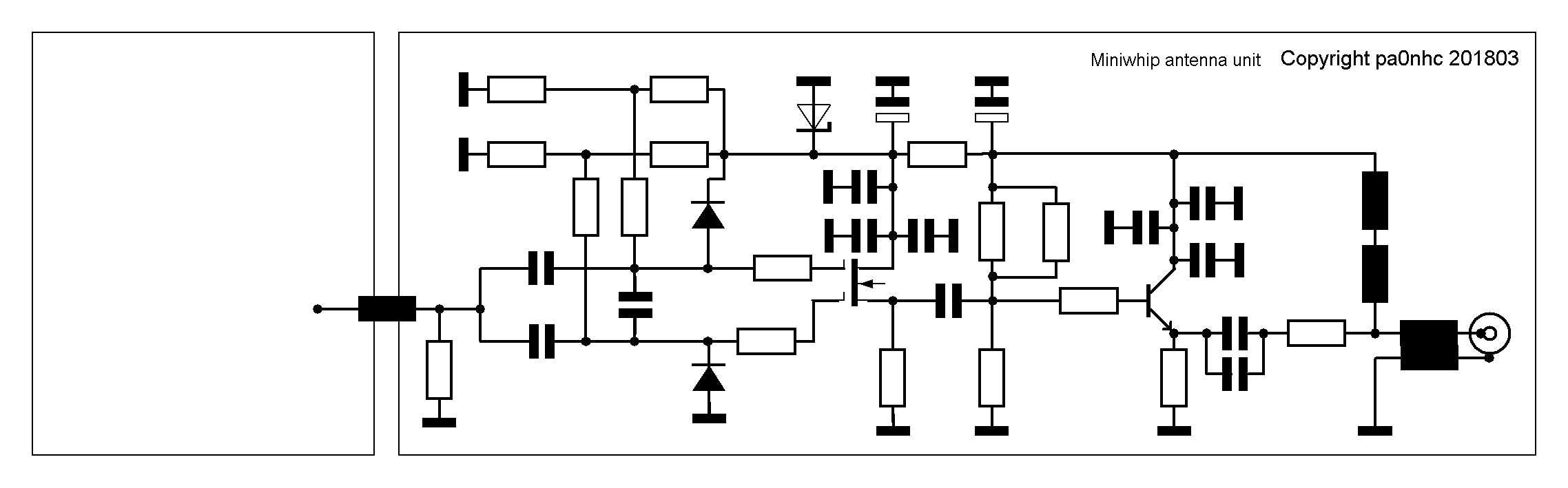
Unique pa0nhc antenna input circuit for highest IMD-free output, widest
bandwidth,
and a wideband output circuit including an effective common mode choke.
|
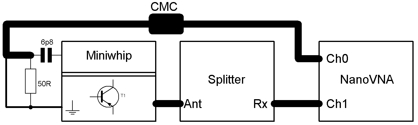
Measured frequency
characteristics (L1 on the antenna PCB is short circuited).
|
|
|
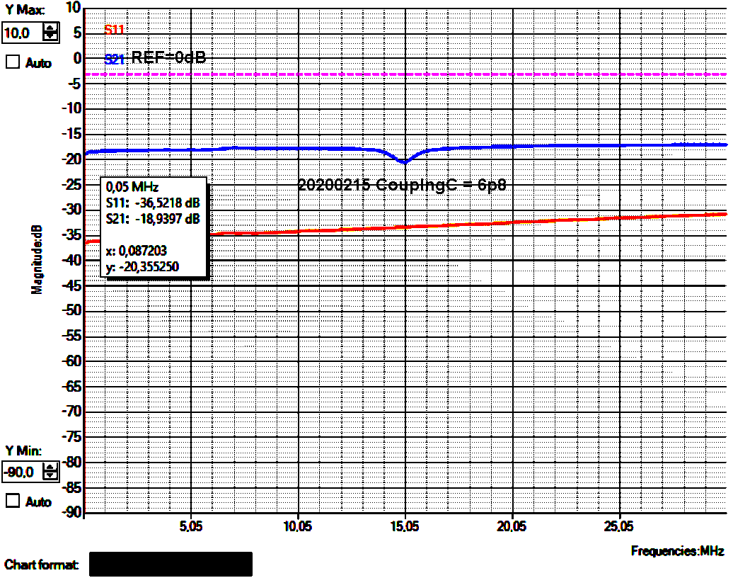
50kHz - 30 MHz.
The -2 dB dip at 15 MHz is a weak choke resonance in the
splitter.
Orange = nanoVNA Ch0 reflection damping
(70cm coax, 50 Ohm // 3p5 coupling).
|
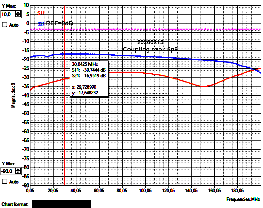
50 kHz to 200 MHz, -3 dB @
147 MHz.
|
|
|
IMPORTANT :
Every active receiving antnna needs careful
de-noising measures.
E-field antennas (like all Miniwhips) also must be
connected to a dedicated NOISEFREE ground.
|
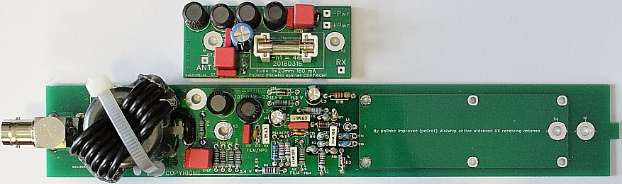
UPDATES 20200828.
Antenna unit.
Common mode choke L5 :
a. For best results ONLY use
#31 ferrite (high
loss Ui=1500).
202008 : FairRite item 2631801202.
If unavailable :
Better
(longer) replacements : 2631101902 or 26311020202
Wind
the coax until the core hole is fully filled.
Every turn must lay beside the former as shown below.
Do NOT cross another turn. |
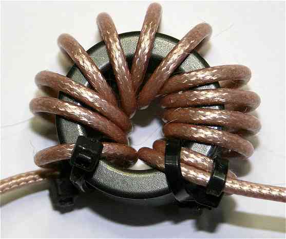
Coax CMC made from 29mm #31 ferrite core
(Fairrite 2631801202)
with
the maximal number of
13 turns
thin 50 Ohms coax (RG316 or RG174 ). |
Splitter
unit.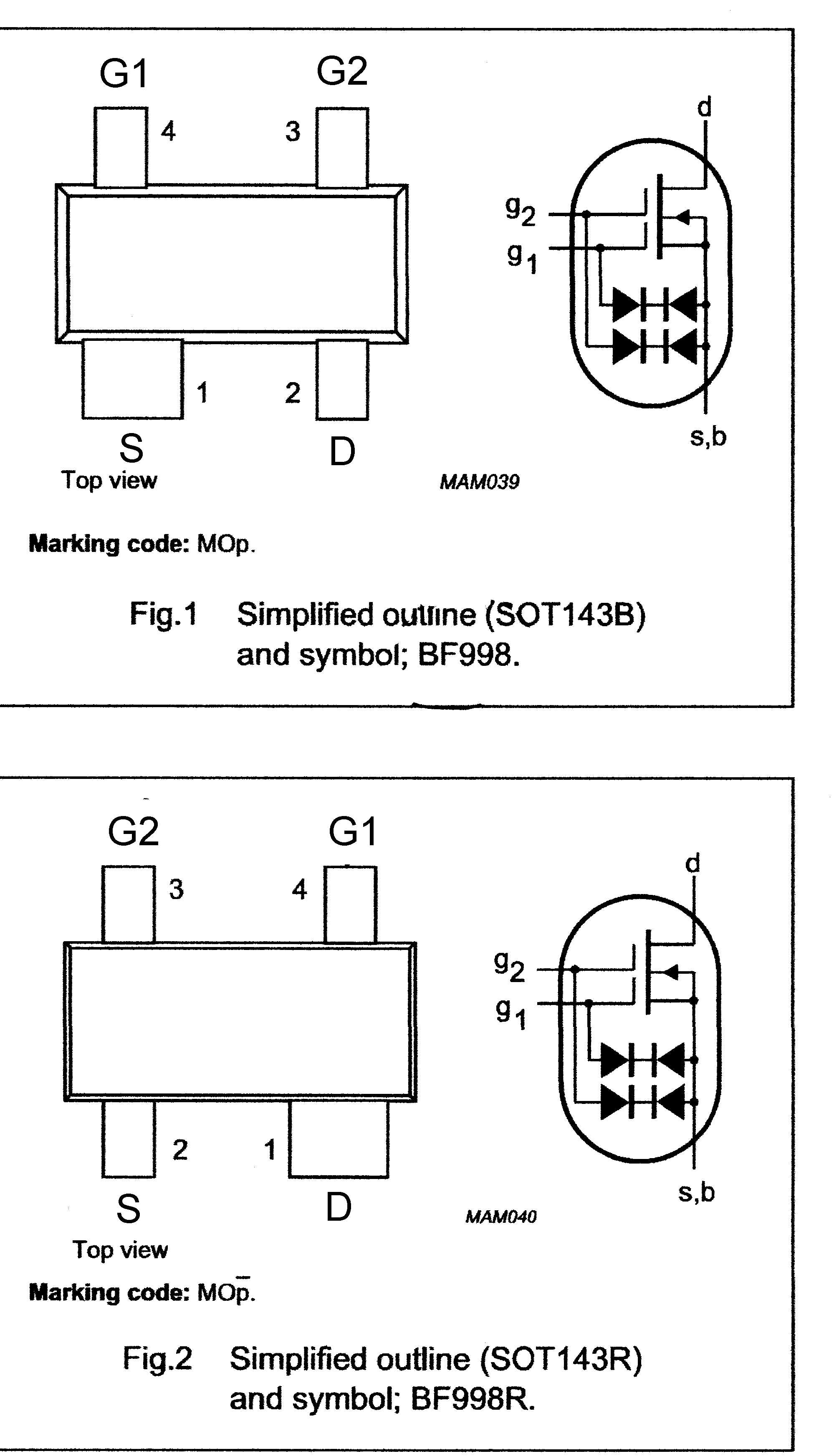
b. Insert an extra choke between the PWR+ connection on the
PCB, and the power+ connection on the PWR-bus.
c. Do NOT connect the PWR-minus point at the
PCB.
The PCB mass planes must electrically only be connected to the INSIDE of
the splitter box through the 3mm screws.
d. The BNC-recepticles MUST be
in perfect electrical contact with the OUTside of the METAL
splitter housing.
e. Use CMC's on all
cables (see de-noising)
f. GROUND the antenna PCB, nothing else..
20240203 : Extra info about the used BF998 dualgate MOSfet :
Two versions of BF998 exsist : version B (fig.1) and version
R 9fig2).
The PCB is designed for BF998B.
But a BF998R can
be used by soldering it with the top in contact with the PCB (topside
down).
|