MiniwhipInstallation.pdf
Common Mode Chokes
This professional PCB is available. With build-in noiseless power supply.
| << |
Local-noise filter pa0nhc
20150718 / 0903
/ 20181207 / 20190801 |
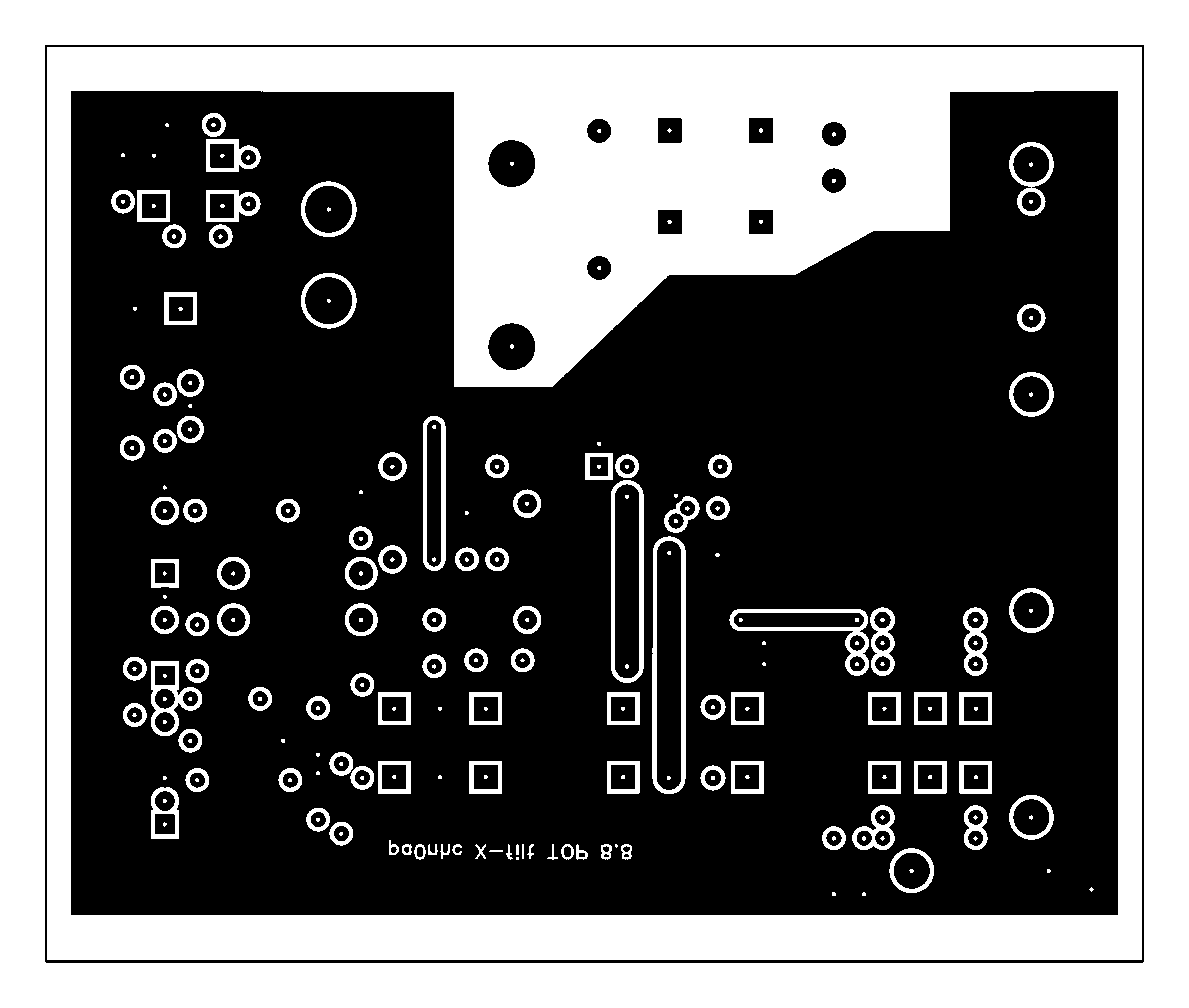
| Bottom Copper MASK 1200DPI |
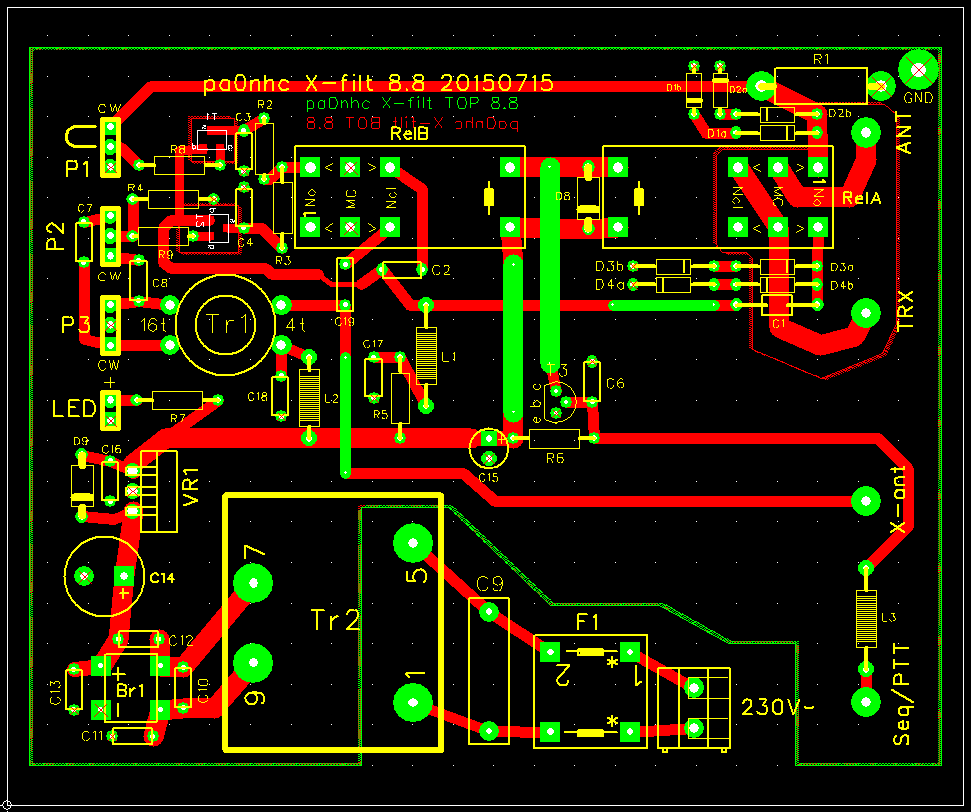
Top copper MASK 1200DPI |
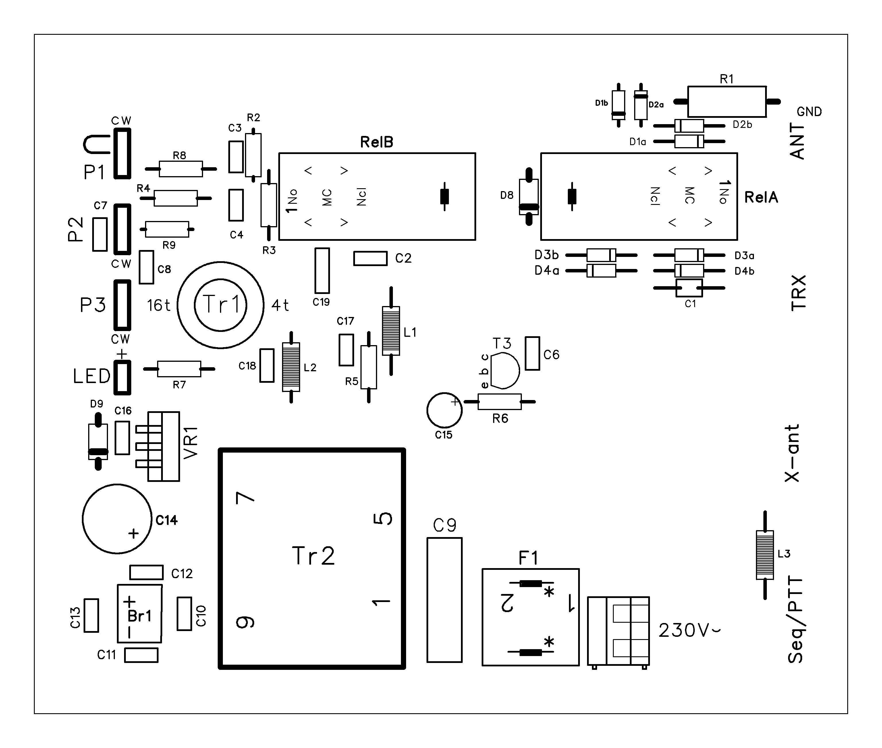
Top silk 600DPI |
XRAY | Schema | "Active noise antenna" | PCB catalog |
Please read other interesting information useable for installing noise killers :
MiniwhipInstallation.pdf
Common Mode Chokes
This professional PCB is available.
With build-in noiseless power supply.
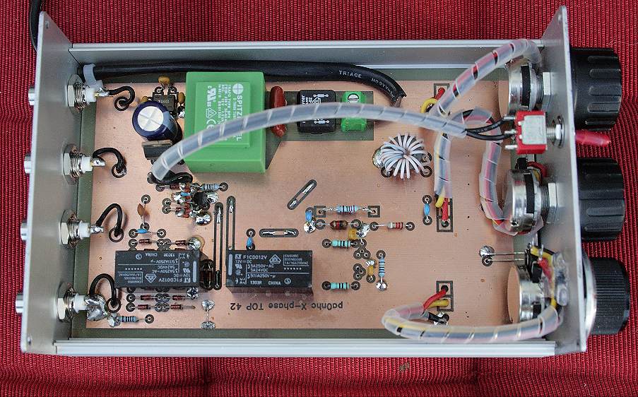
Prototype with home made PCB.
The professional PCB version can be ordered..
Be aware :
The
success of noise killers fully depends on :
- the type of the used noise antenna and main antenna,
- the noise antenna's optimal position and
- the de-noising of the coax connection for the noise killer.
In my experience : A noise killer with a
"VOX" will NOT work satisfying. My version noise
killer therefore has NO VOX.
Instead :
| If this noise killer is used with a receiver
only, the "Xfilt" PTT-input must not be connected. If this noise killer is used with a transmitter, the "Xfilt" PTT-input must be connected to the transmitter's "REMOTE" output (which is designed to switch an external power amplifier from "standby" to "amplify"). Use the connections which will be CLOSED when transmittiing. These "PTT" signals should containing proper delays. |
Optimal antenna combination.
On the low short wave bands (1.8 MHz, 3.6 MHz, 5.36 MHz and sometimes 7
MHz), horizontally wire antennas will receive wanted NVIS signals
These wanted NVIS signals come from (nearly) straight up, at (nearly) 90 degrees
in respect to sea level.
Signals coming from just above the horizon are received weaker by horizontal wire antennas.
A good installed vertical antenna (MINIWHIP)
however, does attenuate the NVIS signals with more than 20dB.
Noises (and signals) from sources just above the horizon will be received by
vertical antennas strongly.
When using a horizontal wire antenna as main
antenna, best use a vertical active antenna as noise antenna.
For good results. try a good and exactly vertically installed MINIWHIP,
placed far as possible from the main antenna, and close as possible to the noise
sources.
When using a vertical main antenna (mast, GP),
best use a horizontally installed MINIWHIP as noise antenna.
Place it far away from the main antenna, nearby as possible to the noise sources,
for best results.
|
Relay actions. 20190905 If power is available, When PTT is shorted to GND,
relays are not energized, and relay A connects TRX to ANT. No RF can
go into T1. Faulty condition : |
My experiment :
My location suffers from a high noise level, all metal structures, mains and safety ground are radiating noises. With no obvious source. I now am listening and transmitting at 80m
en 40m using a tuned, fixed located loop antenna of 3m diameter. Earlier, using an active wideband receiving antenna, the local noise level was S9+20dB op 3,65MHz.
Currently listening with the loop antenna, this noise level dropped remarkably to S7. On 40m i have a lot of noises from some digital carriers up to S6.
Worse : An plasma TV in the living room is only a few meters away from the loop. This TV showed to be a strong and complex interference source. Inducing S9 noise on 80m, and S6 noise on 40m. With minimum contrast a buzz is heard, with maximal contrast a strong rattle. A visiting Panasonic service technician stated : "We have no solution for this". As it delivered me a superb picture for 5 years now, and my wife does not want to invest for a new TV, another TV will not be bought. So i had to find a solution myself.
I decided to try the DK9NL "X-phase" noise killer. After some modifications to the filter circuit, and a lot of experiments with noise antennas like whips, loops and ferrite antennas, i succeeded using my new developed active ferrite "Noise antenna".
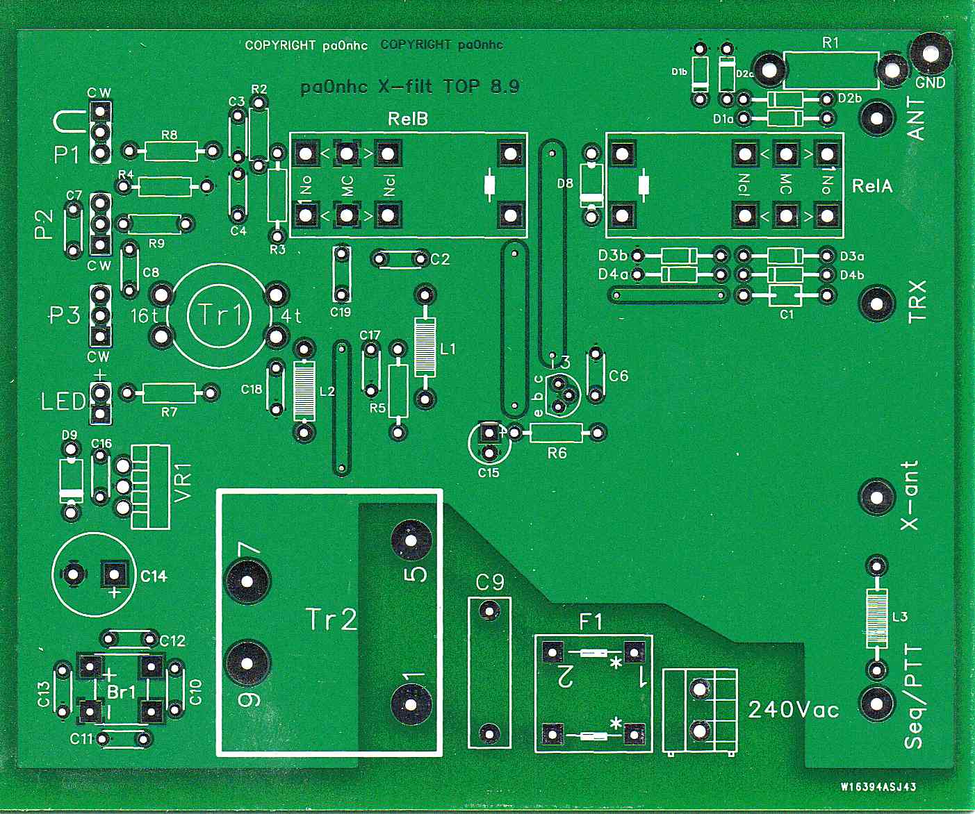
The double sided filter PCB can also be used single sided. On its copper-less top, four wire bridges have to be placed (see the green tracks in "XRAY"). Nearly all components have wires. The only two smdFETs are soldered at the bottom, all other components are placed on top. This PCB is designed to fit in a Proma 130040 ALU cabinet. The PCB can be cropped to 113.344mm x 89.92mm, by removing the isolating borders for other housings.
Only 2 SMD components are used : two small BF999 FETs. The simple but effective power supply is fully noise free. It uses a small and flat 1.5VA transformer. When connected only to the receiver, even tuned to a busy 40m band, the prototype was completely silent.
Below some components are given with ordering numbers (www.conrad.com) for your convenience. I selected them for usefulness, low price and availability. They will fit to the PCBs,
| P1-3 | MUST be of good quality. | (440878) | |
|
Tr1 |
Ferriet ring Amidon FT50-77, u=2000, d=12.6mm, | pri 4t, sec 16t (www.amidon.de). | |
| Tr2 | Power transformer (1.5VA) | Spitznagel SPK01412 | 556938 |
|
Ch1 |
Mains filter | (Schaffner RN102 1 02) | 398686 |
| RelA, RelB | 12V relay DPDT 2A/250V~ | (Fujitsu FTR-F1C) | 502998 |
| Br | DIL rectifier bridge 1A | (DIOTEC B40D) | 501204 |
|
L1 |
Ferrite choke 1mH axial 3mm dia. RM10 | (Fastron MICC-102K-02) | 440364 |
|
L2 |
Ferrite choke 100uH axial 3mm dia. RM10 | (Fastron MICC-101K-02) | 440377 |
| L3 | Ferrite choke 10uH axial 3mm dia. RM10 | (Fastron MICC-100K-02) | 440390 |
|
VR1 |
Stabilizer 12V, low drop | (LM2940CT-12) | 1013996 |
| C9 | Mains filter capacitor 0,1uF 275V~ RM15 | 1235278 | |
| L1(ant) | Ferrite antenna rod 8mm x 50mm u=300 | L1=50t 0.7mm | 535575 |
|
L2(ant) |
Ferriet choke 22uH radial RM5 d=8.7 | (Bournes RLB0914-220KL) | 1056028 |
|
ALU box |
For the filter circuit | Proma 130040 | 522945 |
|
Black plastic box |
For the noise antenna | (Hammond 1591MBK) | 520675 |
REM: if used above 7MHz, "L1(ant)" could be wound on a Amidon rod with u=125 (material 61). The coil should self-resonate halfway the used frequency range. R1 should be adapted for low Q.
|
TIP : It is wise to put "ferrite clamps" (dividable ferrite rings)
or ring cores on These
common mode choke clamps or rings should be made of Fair-Rite
MIX
#31 material . Order at ARROW.COM . |
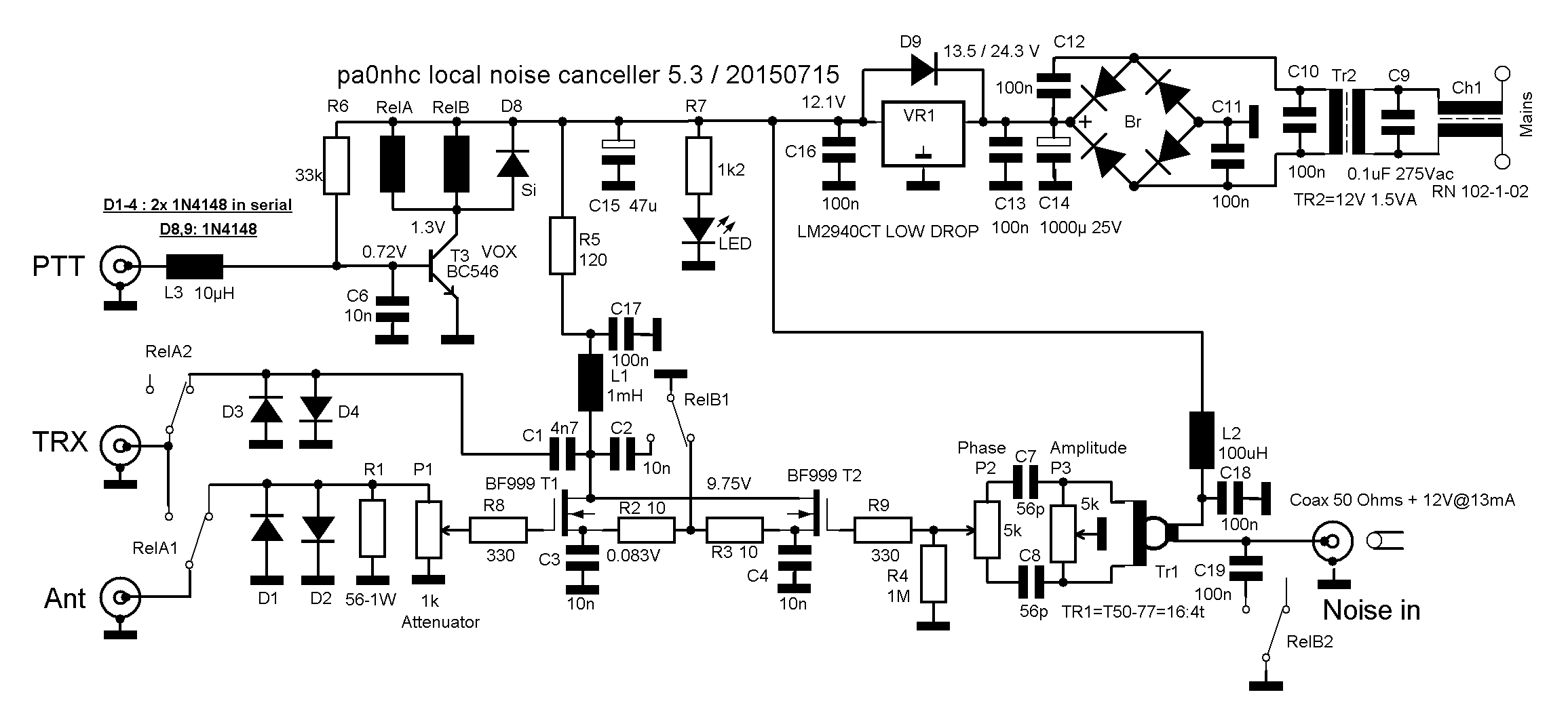
Filter schematic.

Filter adjustment.
Attenuating the main antenna signal by P1 only is necessary, when the noise antenna delivers a to weak signal. Then readjust the position of the noise antenna.
I had good results with the noise antenna taped to the center of the back of the TV, with the ferrite rod vertically.
a. First tune the main antenna correctly. A detuned antenna can be of influence to the amplitude and phase of the received (noise-) signals.
b. Switch the AGC to slow action.
c. Set P1 at max.
d. Turn back the RFgain to S9 or higher. Turn up the audio gain accordingly.
e. Set P2 and P3 in their mid position.
f. Adjust P2 (amplitude) for best noise rejection.
g. Adjust P3 (phase) for best noise rejection.
h. repeat "f" and "g" several times for max. noise suppression.
You now should hear only the bands background noise.
Filter unit circuit description :
This conventional power supply only consumes 1.5VA. The mains voltage is filtered by CH1, C9 and the separated windings of TR2. Four capacitors at the bridge rectifier prevent
rattle and IMD. The voltages are safe for the used FETs (max 8V).
The signal from the main antenna ("ANT") is fed unfiltered (wide-band) to T1. It can be attenuated by P1. This only is necessary if the signal coming from the noise antenna is weaker than the noise on the main antenna. The drawback is that the wanted signal also is weaker, and a correct signal strength report cannot be read.
For the FETS the modern BF999 is chosen, for its low price, and at 0V gate voltage it has the high steepness of 20mS (20mA/V) and draws only 10mA. T1 therefore amplifies 0dB (1X) when "TRX" is connected to a 50 Ohms load. The positive result is, with P1 at "max", no signal differences is noticed when the filter unit is switched on/off. For D1/D2 two high speed diodes in series are used to enhance IMD performance up to S9+80dB.
The "Active noise antenna" is connected to "NOISE IN" via a thin 50Ohms coax (RG174).
After passing the phase shift circuit (Tr1-P3-P2), the noise signal is fed to T2. P3 and P2 adjust the phase and amplitude difference between the main antenna and the noise antenna. As the secondary winding of Tr1 is nearly not loaded, Tr1 also introduces a wanted phase shift of 90 degr; so P3 is more in the mid position.
Both signals "ANT" and "NOISE IN" are combined at L1. The noise on the main antenna is fully suppressed if the signal of the noise antenna is exactly equal in strength, but exactly 180 degr. out-of-phase with the noise on the main antenna. All other signals at the main antenna are not influenced and will be routed to "TRX".
The T/R circuit
(T3) without VOX.
In the original design from DK9NL a rf-detector was switching-on T3 if more than 10W power was present on "TRX". Consequently the relays switched when RFpower already
was present, and they rattled during talking-pauses. Possibly causing wide band
RF-switching noises.
The only proper way for switching the noise filter unit between receive an transmit, is by an external command from "Power amplifier control" output of the used transceiver, or from a dedicated "Sequencer".
It should connect "Seq" (PTT) to mass, en contain the correct delays. The transmitter may only deliver RFpower a short while after all relays are switched from the "Receive" position to the "Transmit" position. The relays may only switch back to "Receive" after a short while that the transmitter seized delivering RFpower.
The present circuit therefore does NOT contain a "VOX".
When Input "PTT" is not connected to chassis, R6 opens T3, and relays A and B are switched to the "Receive" position (like shown in the schematic diagram). If a sequencer or transmitter connects "PTT" to chassis, T3 closes, the relays fall back in the "tramnsmit" position, and input "TRX" is connected directly to "ANT".
D1/2 are each two fast SI-diodes in series. The prevent damage to the gate of T1.
D3/4 are each two fast SI-diodes in series. They prevent damage to the drains of T1 and T2, if power is put on "TRX" while the relays are not switched to
"transmit".
D8 damps relay coil switching pulses and enhances their switching speed.
D9 prevents damage to VR1 if its input voltage becomes lower than its output voltage.
The relays consume nearly 80mA, the FETs 18mA, and the noise antenna 13mA. The small 1.5VA power transfor Tr2 just can deliver that. REM: use a low drop regulator for VR1.
R8/9/11 are "stop" resistors, preventing parasitic VHF oscillations. They act as a low-pass-filter together with the input capacitances of the transistors. Higher values than shown here can lead to higher self-noise or signal loss at high frequencies.
R2/3 ensure a lowest-impedance-path is via C3/4. Also preventing possible oscillations due to the self inductance of the relay connections.