|
Calculated loaded
loop Q (formula
according to
DL4KCJ) :
Q = Xc / Zraam. B =
F / Q.
7,1 MHz : Q = 299 / 5,5 = 54. B = 7100
/ 54 = 131 kHz.
3,65 MHz : Q = 208 / 0,61 = 340. B = 3650 / 340 = 10.7 kHz.
Due to the relative large loop
circumference (> 1/20 lambda circumference), the feedpoint-Z is HIGH,
resulting in low
loop Q, low loop currents, and high efficiency.
With optimal matching circuit having tight coupling between the matching
circuit and the loop feed point.
Antenna bandwidth and selectivity (3700 kHz).
Magnetic transmitted field strength
bandwidth measured in the antenna near field :.
-3dB @ 3680 kHz and -3 dB
@ 3720 kHz (40kHz).
Selectivity : Received signal strength
:
-20dB @ 3800 kHz and -20dB @ 3600 kHz (200
kHz).
Cross band selectivity :
Very favorable for co-site
operation
(field day / multi antenna club
station).
Antenna tuned to
40 m :
RX signal strength on 80m
-35
dB
!!
Antenna tuned to 80 m :
RX
signal strength on 40m -40
dB !! REM
: my coax feeder is about 19m long. Measurements
were not done at the antenna, but at the beginning of the feeder.
The VSWR properties of this loop are better than here measured !
Measured antenna bandwidth for
VSWR < 1.5
Antenna fixed tuned to 7,1 MHz :
B(vswr<1.5) = 70 kHz.
Antenna fixed tuned to 3,7 MHz : B(vswr<1.5) = 8
kHz.
REM : On 80m still enough bandwidth exists for good SSB and AM performance. Measured
tuning range for VSWR < 1.5
:
(3.0 to 4.4 MHz) and (5.3 to 9.1 MHz).
This is FAR WIDER than of a 1/2 wave dipole antenna.
In these large tunable ranges the feeder VSWR and feeder losses are
LOW. Loop is tunable
to resonance between 3.0 MHz and 9.95 MHz.
|
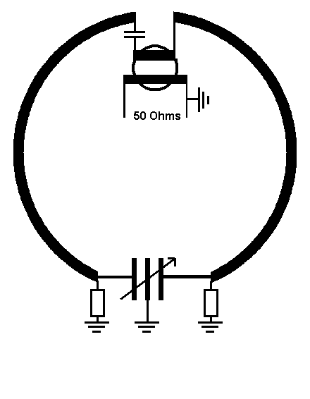
New
matching system.
Pure resistive transformer =>
Lowest
VSWR = max.radiation.
Symmetrical feed into
the loop current center
=> NVIS.
Good.
|
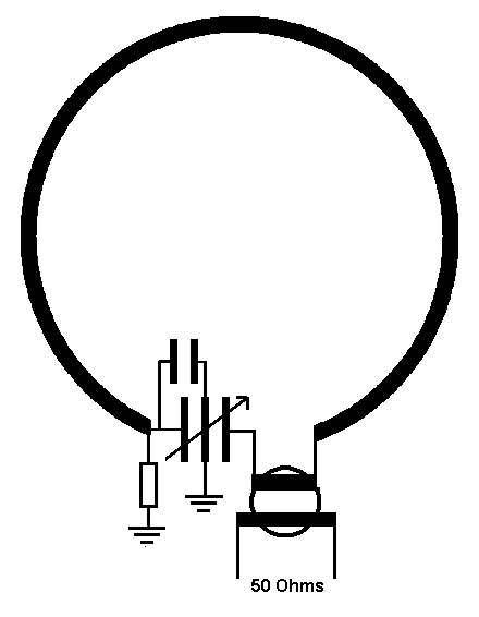
(Old matching system)
Asymmetrical power injection.
=> Skewing radiation.
Transformer not optimized.
=> Max field strength
<>
lowest VSWR.
Wrong.
|