|
REM : "R" is not installed. |
|
|
|
|
|
See these dimensions as a
starting point. 1. First adjust C3 and C4
for resonance at |
| << |
A new idea
for a very small omni directional 145MHz antenna. pa0nhc. |
A
sturdy and stealth, horizontally polarized, OMNI directional, fully balanced
145 MHz antenna.
For low power
ARDF TX, foxoring TX, or a hand held two way radio.
|
REM : "R" is not installed. |
|
|
|
|
|
See these dimensions as a
starting point. 1. First adjust C3 and C4
for resonance at |
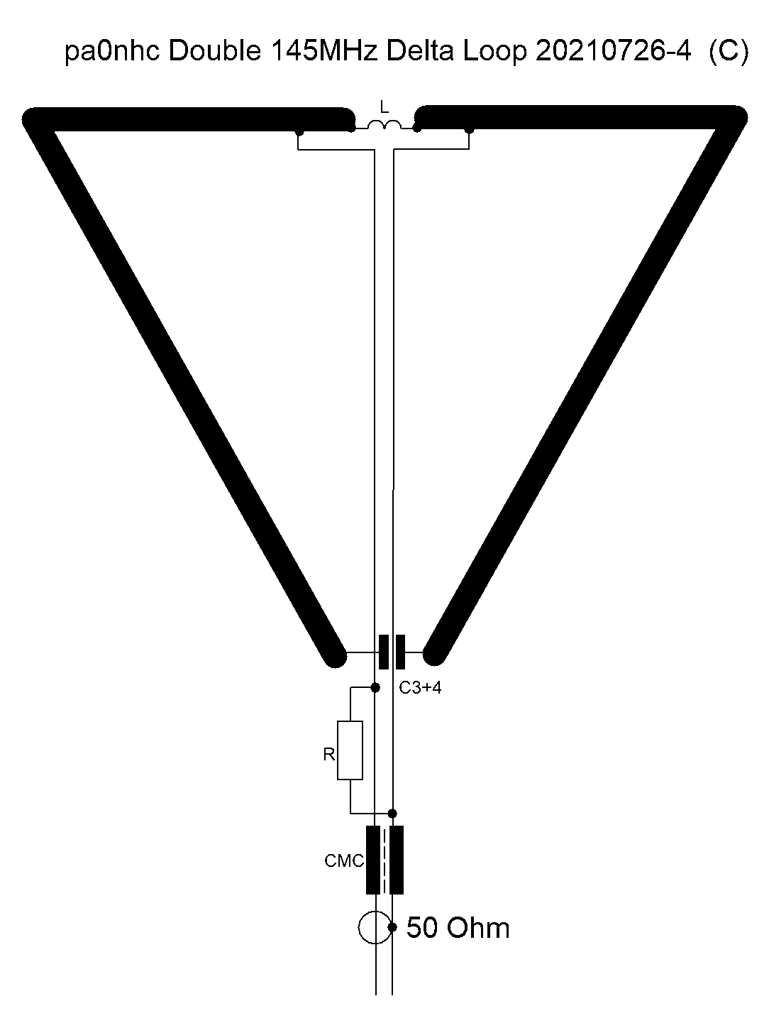
This is a 145MHz delta loop with delta matching. I
called it "The Double Delta Loop".
This very small 2m band antenna is constructed on a 162x195mm
PCB card. ©
This omni directional antenna needs no phase lines etc.
Updated 20210828.
| pa0nhc PCB service © New 3th PCB version 20210726-4. |
This very small size 165mm (6.6") wide and 195mm (7.6") long, sturdy and light weight (50g) omni directional narrow band 145MHz antenna, is less suspicious and easy to install at a site. It can be used as a nearly invisible horizontally (or vertically) polarized antenna, horizontally or vertically mounted beside a thin (fiber) mast. Useable for a low power foxhunt transmitter, or for a two way portable radio.
A build-in Common Mode Choke prevents influence from common mode currents on the outside of the coax feeder. When the antenna is at least 1m free from surrounding objects, it has a clean omni directional pattern. It is the antenna's own property, without the need of phase lines etc. The 60 degr. top of the loop and both sides should stay at least 20cm away from conducting objects, to prevent de-tuning of the high-Q loop. The coax should run at an angle of 90 degrees away from the loop base (the hair pin matching coil), to avoid magnetic RF coupling between the connected coax and the loop.
All PCB material
was removed just outside the copper tracks, and small components are installed,
to minimize the weight of the antenna to
about 50 gram.
All corners are rounded to prevent problems with catching twigs and
leaves.
A rectangle shaped extension enables fixing the antenna to a boom, mast or directly to a transmitter.
|
|
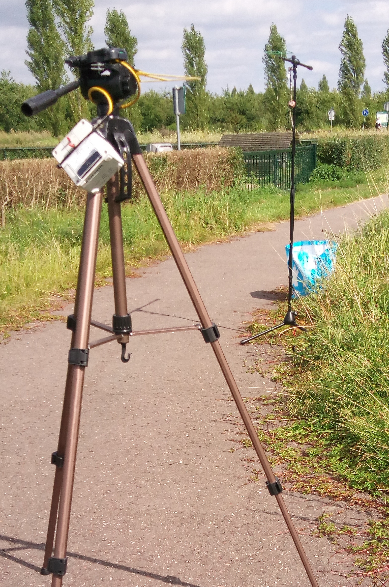
In a reasonable open field,
I tried to measure
the horizontally polarized directivity patterns of both 2m loops. Touching the measured antenna coax feeder had no influence on meter readings. I observed at both sides of the delta loop 3dB less signal strength, compared with its front (arrow) and back. Is is a nearly omni directional pattern with only 3 dB signal strength variation. The
square loop showed also to be an omni directional antenna. |
|
Properties.
This antenna is an at 145MHz resonating, high-Q, narrow band delta loop, with nearly a 1/4 wavelength circumference. The loop conductor width is 10mm. The element conducting surface equals
therefore to that of a 6.4mm thick copper tube. The loop copper conductor is effectively protected
against humidity and oxidation by the PCB solder mask. The delta match, the transmission line, and
the common mode choke are all
carefully designed and constructed to be balanced and to have 50 Ohm impedance at 145 MHz. A very effective common mode
choke "CMC" is inserted, between the balanced transmission line on the
PCB, and the external coax cable. The always present common mode
currents on the outside of the coax screening can therefore not disturb the
smooth radiation
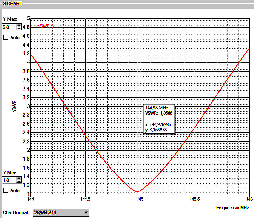
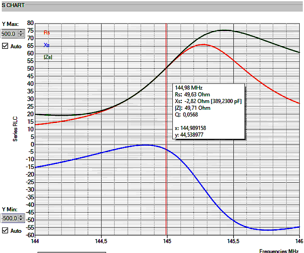
pattern of this antenna. This high-Q antenna system has a bandwidth
of abt. 1MHz for -3dB. The antenna should therefore be tuned to the wanted band portion.
The high antenna-Q surely helps improving the RF selectivity of a receiver,
and suppresses harmonics of a transmitter, without additional filter losses.
Antenna gain could be created by stacking 2 or 4 DeltaDelta loops above each other, at distances of 65cm. Feeding all antennas with equal lengths of coax. Matching it with a 1/4 wavelength coaxial transformer : 2x75Ohm coax in parallel for 2 antennas, 2x 50 Ohm coax in parallel for 4 antennas.
The important common mode choke (update 20210724) ©.
|
|
|
|
|
|
Ferrite core : FT50-61 or equivalent (1/2" or 12.5mm diameter,
1/4"or 6.25mm thick, ferrite mix #61, Ui=125, Al=69), from Amidon, FairRite
or Micro Metals.
The properties of this CMC depend on its careful construction !
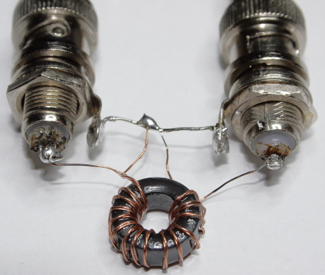
CMC construction :
1. Fold 80cm of 0.25mm thick lacquered copper wire,
into a
40cm long parallel wire pair.
2. Firmly twist this pair 40 times. Kinks are not allowed. (use an electric
hand drill and vice).
3. => Count how many times the wire pair goes through the hole
of the core <=
Wind this twisted wire pair 15 times through the hole of
the core.
Every individual wound turn should be pressed close to the core
surface.
Be sure there is no free space between the turns and core
body, to prevent water intrusion and change in impedance.
After painting, no water may come between wire and core.
Turns may NOT overlap, but must lay beside each
other..
All turns must be evenly divided over 270 degr. of the core circumference. See
photo ===>>
4. Paint all turns, and core, at least 3 times with
transparent nail lacquer "Top Coat".
Spaces between wire and core should be filled with lacquer.
Let dry between paintings.
Once finished,
let dry at least 12 Hrs as this has influence on its properties.
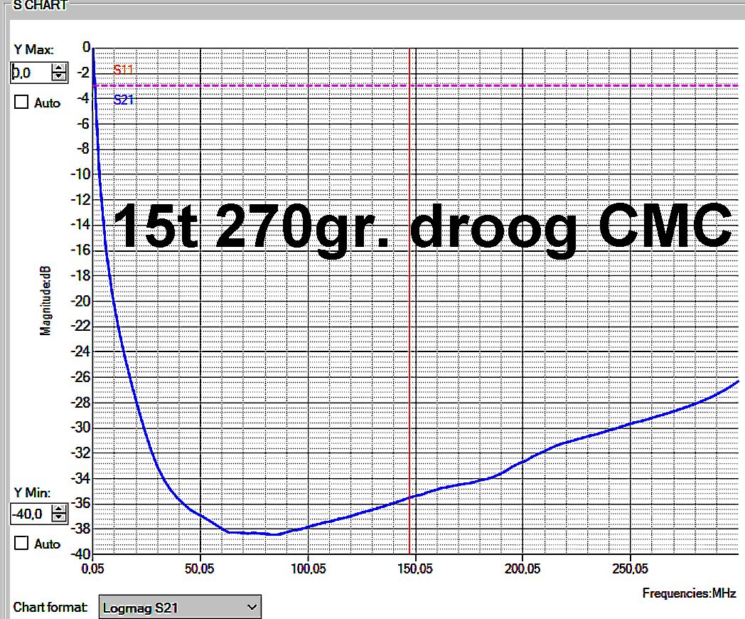
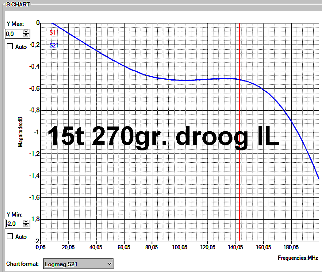
5. Check the common mode and line impedances of the dry
coil (see graphs
above).
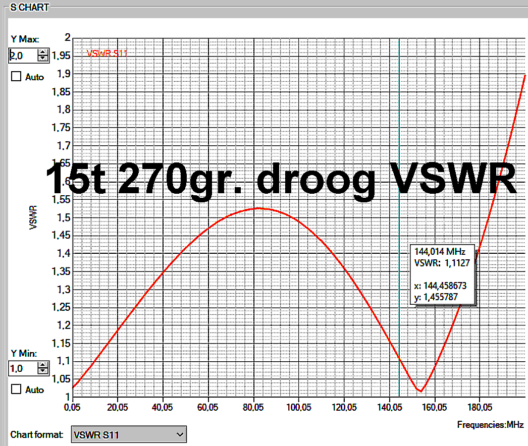
The lowest VSWR value of the CMC alone should occur
around 145 MHz (see VSWR graph).
6. Solder the finished CMC in place. Keep pigtails twisted
and short.
Glue the CMC to the PCB with
again a few layers Top Coat. See photo.
Matching inductance L.
This loop is matched to a balanced 50 ohm transmission line by a "Delta
Match". It consists of two taps, symmetrically left and right from the
center of the loop conductor. Experiments and measurements to get the correct positions for the
taps
are time consuming, and expensive due to different versions PCBs (about 65 Euro for each new
single PCB design (PCBfactory, DHL, Customs !). Very small changes in dimensions have influence on the
loop performance. So, after ordering a new loop PCB, it is NOT sure that the
results will be as experimentally reached.
I therefore choosed for a "hair pin" match.
It enables easy tuning to best VSWR. You
could think about it as an adjustable loop lengthening piece at the center of the
loop. By changing its dimensions, perfect match can be
achieved. AND : its is predictable and dependable. BUT also of influence to
the loop resonance frequency.
Installation of L. The
properties of the loop depend on its careful adjustment ! By copying all
dimensions, result is fast.
1. First install C3 and C4 (3p3 and 56p).
If wired Cs are
used, shorten these wires AT ABSOLUTE MINIMUM. Better use SMD capacitors.
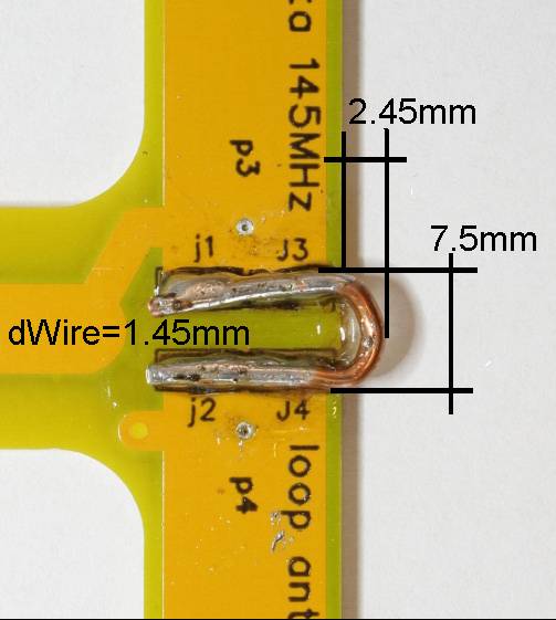
2. Bend a U shaped piece of 1.45mm thick copper wire as shown in the photo. Be sure about correct dimensions.
3. Solder it in place at the PCB.
Be sure to start with 2.45 mm distance
between the PCB outside and the outside of the hairpin. Critical
!
Measure it
with a caliper.
All 8 solder pads on the PCB should be well soldered to
the hairpin.
4. Connect a 70cm long (= 1/2 lambda long) 50
Ohm coax cable (RG316 or RG174).
Use a VNA (cheap
NanoVNA) to measure the resonance (lowest VSWR)
frequency (to begin it should be between 142MHz and 148 MHz).
If not, correct the resonance
frequency first with C3/4. See [6].
5. Measure the loop VSWR.
If it is higher than 1.2, de-solder the matching
inductance L and reposition it a little.
Change the distance between
PCB border and hairpin outer surface.
Check VSWR again.
Repeat [5] until VSWR <= 1.1 .
6. Check the resonance frequency (frequency of lowest VSWR
value).
To high ? => solder a small value capacitor in parallel to C4.
To low ? => replace C4 by a bit smaller
value capacitor, and place a small value capacitor in parallel to C4.
Repeat [6] until OK.
Design details.
|
When developing this small 2m loop, i used
the research done by G0CWT,
and my experiences
with optimizing my 40-80m TX loop. |
In the center of the top of my loop is the RF current maximum, which is also the low impedance feed point. The symmetrical delta (NOT asymmetrical gamma) match at the loop feed point, matches the loop impedance to a balanced 50 Ohms transmission strip line. which is running trough the center line of the loop, from the top to the bottom end of the antenna. This balanced 50 ohm PCB strip line is used, to avoid coupling with the loop.
Without a CMC in the transmission line, distortion of the radiation pattern of the antenna will occur. Then not only the loop, but also the coax is radiating or receiving. With a good CMC inserted, this will be prevented.
At the bottom end of the balanced PCB strip line, a
50 Ohm
Common
Mode Choke ("balun") is therefore inserted.
It also functions
to convert the balanced
"two wire" 50
Ohms line, to an unbalanced 50 Ohms coax line.
Important : To avoid electro-magnetic RF coupling between the connected coax and loop, the coax should run at an angle of 90 degrees away from the loop.
Please read : Balancing and closed loop antennas (pa0sim.nl)
Weather proofing.
Paint all components and connections with transparent nail lacquer ("Top Coat"). Use it also to
glue
the CMC to the PCB.
Be sure no water can
intrude the connected coax, nor the CMC windings, nor between C3 /4 and the PCB.
Water intrusion can cause a massive
change in transmission line impedances and large losses.
Let dry the paint, as this has influence to the properties of the antenna.
Measuring tips :
Mass contact resistances in BNC to SMA
adapters can cause unreliable measuring results, especially when measuring VSWR, IL and resonance.
Use good quality, machined connectors of well known brands. Do not use die castled, nor nickel plated, cheap Chinese junk. They will create diode contacts, and often even miss the machine sawed slits in de mass contact bus.
Apply to all connectors a little oxide and sulfide removing, contact improving
fluid, like CRC
2.26. (Do not forget USB).
After that, loosen and remove oxides etc, by turning the BNC bayonet rim round, and
pull BNC plugs in-out a few times.
REM : do not use CRC2.26 on motor/dynamo
commutators, nor on coils or trimmer capacitors.
This fluid evaporates partly and very slowly, leaving a little anti-oxidation
oil => causing shifting resonance frequencies.