|
|
| << |
Wrong and correct calculations for |
Magnetic loop calculation software presumes that the
RF-current has a constant value everywhere around the
radiator.
This assumption (only) gives useable results for very small loop antennas, with a circumference smaller
than 1/20 lambda.
But a maximal large 1/4 lambda circumference capacitive tuned loop has very different properties
:
|
Example : A tuned 1/4 lambda circumference loop antenna.
|
The loop currents recalculated using practical impedance measurements by G0CWT :
|
|
Using an antenna analyser, G0CWT measured in the current maximum of a resonant 1/4 lambda loop a feed point impedance of 5.5 Ohms.
From this and the 100W transmitter power, we can calculate
with ( I2 = P / R) the
RFcurrent there as
4.26A.
=> This
is half the value calculated by 66pacific.
Near
the tuning capacitor, G0CWT measured a feed point impedance of 22.5 Ohms.
From this the RFcurrent at the tuning capacitor can be calculated as
2.11A.
=> This is nearly 5x smaller
than calculated by 66pacific.
The capacitor voltage
recalculated.
The 63pF tuning capacitor shows at 7.1MHz a reactance Xc=365 Ohms.
With the above calculated 2.11 Arms RF current through the tuning capacitor, the voltage over the capacitor is (365 Ohm x
2,11 A) = 770 Vrms or only 1090 Vp.
|
|
=> This is nearly 5x lower than calculated by 66pacific.
=> Conclusion : a vacuum capacitor tuning is NOT needed, a transmitting air tuning capacitor could be used for 100W power.
Bandwidth.
In practice
my loop has on 40m a
"VSWR < 1.5
bandwidth" of 75 kHz. According to DL4KCJ this cannot be used to calculate the loop-Q.
But
this practical bandwidth is more than 3 times wider than calculated by 66pacific.
Important conclusions :
1. The value of the RF current near the tuning capacitor is half the value
of the RF current in the top of the loop. RF currents therefore have NOT the same value around
a 1/4 lambda loop
circumference.
2. The values of RF currents in a 1/4 lambda circumference loop are lower than in smaller sized loops.
Resulting in :
less losses,
lower Q,
larger useable bandwidth
smaller copper diameter needed
simpler tuning capacitor and its
mechanical reduction is possible.
Still not convinced ? Compare these results with calculations after DL4CKJ.
|
|
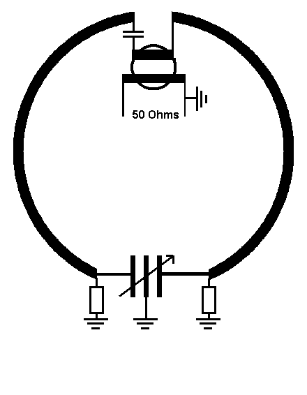
Matching a 1/4 lambda circumference loop antenna.
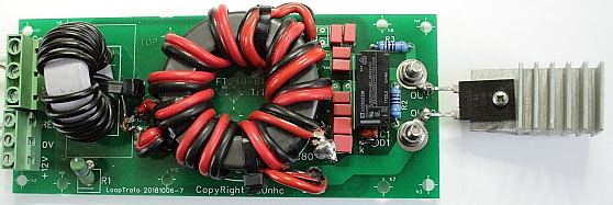
G0CWT uses a broadband ferrite core transformer to match the 50 Ohms coax feeder to the
loop.
A suitable transformer
circuit can be inserted in any point
around the loop circumference :
- in the current maximum or
- in the voltage maximum or
- in-between.
For these
three cases, the feed point impedances will differ.
|
Connecting the matching
transformer to the lowZ top of the loop, gave me in practice the best
results. This new coupling circuit ensures a fully BALANCED excitation of the loop, resulting in no power unbalance, nor capacitive unbalance, and pure magnetic behavior. |
My loop has 10m circumference, this equals 1/4 lambda for 40m.
G0CWT measured
at the current maximum of such a 1/4 wave circumference loop an impedance of
5.5 Ohms.
Matching with a transformer : Zpri : Zsec = 50 : 5.5 = 9.1 : 1 =>
Pri turns : sec turns = 9 : 3
Matching on 80m.
On 80m the circumference of the loop is only 1/8
lambda. Its feed point impedance then drops by a factor 9.
By adding a tap on the secondary winding good match is possible om 3.65 MHz.
Zpri : Zsec = 50 : (5.5 / 9) = 81 : 1 => Pri turns : sec turns = 9 : 1 .
For a detailed description of the matching system : see
designing the
matching transformer.