|
|
|
| << |
Designing a matching transformer for a 10m circumference 40-60-80m loop. |
|
|
|
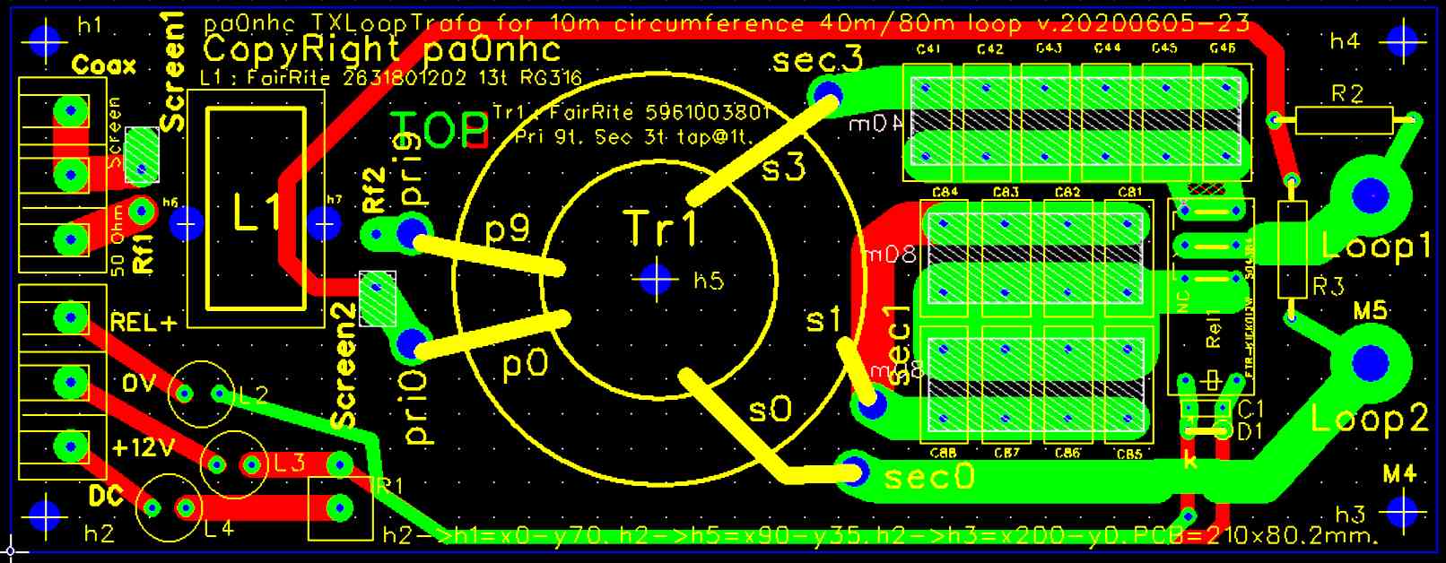
The transformer ferrite core.
A transformer made with a
61mm MIX#61 ferrite ring core (Fair-Rite Part Number: 5961003801)
proved me to be the only suited for a transformer which magnetically
couples RF energy between feeder and antenna.
Up until 20 MHz, it has low loss and good temperature stability. Its temperature coefficient is very low and the Curi temperature is very high. The transformers inductance will vary only very little between -25C and + 150C, resulting in temperature stable properties. The max flux of the core is 25mT, allowing maximal 400W RF power.
|
Warning
: applying more than 400W power at 80m
can cause magnetic saturation of the ferrite core. |
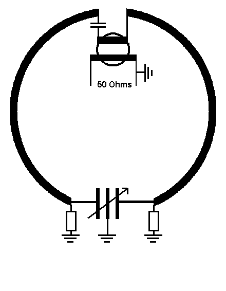
The
feed point impedances of a 10m circumference loop.
G0CWT measured in the current maximum
of an 1/4 wave lambda loop a feed point impedance
of 5.5 ohms.
A matching transformer for a 10m circumference loop, tuned to 7.1 MHz, should
therefore have an impedance ratio of 50 : 5.5 ohms.
Its turns ratio should be : SQRT(50 : 5,5) = SQRT(9 : 1) = 3 : 1.
1/8 lambda circumference loop :
The feed point impedance in the current maximum of
an 1/8 lambda loop is 9.3 times
lower (0.59 ohms) than in an 1/4 lambda loop.
A matching transformer for a 10m circumference loop, tuned to 3.65 MHz, should
therefore have an impedance ratio of 50 : 0.59 ohms.
Its turns ratio should be : SQRT(50 : 0.59) = SQRT(85 : 1) = 9 : 1.
The actual number of
turns for a practical transformer.
1. The parallel winding reactance of a transformer winding should be at
least 4 times higher than its loading impedance.
2. The number of turns must be kept minimal for low leakage
inductance..
3. The smallest possible number of turns for a winding is 1.
4. A secondary winding of 1 turn on a 61mm #31 ferrite core shows
at 3.65 MHz a parallel Xl of 3.7 Ohms,
which is 6 times higher than the 0.6 ohm loop load
impedance.
5. The 80m secondary winding therefore consist of 1 turn.
6. For 40m then are 3 secondary turns needed.
7. The total secondary winding therefore consist of 3 turns, with an 80m
tap after 1 turn.
8. As the winding ratio for 40m is 3:1, the primary winding consists of 9
turns.
Winding inductance and reactance check :
- Xl of every transformer winding should be
at least 4x higher than its loading impedance.
- L = n2 x 0.17 uH.
- Xl = 2 x 3,14 x f x l .
3.5 MHz :
Primary 9 turns. L = 13,8 uH.
Xl = 304 Ohm +- 25%..
Xl : Zload = 304 / 50 = 6,1.
Secondary : 1 turn. L = 0,17 uH +- 25%.
Xl = 3,7 Ohm +-25%.
Xl : Zload = 3,7 / 0,59 = 6,3
7 MHz :
Primary : 9 turns. L = 13,8 uH.
Xl = 607 Ohm +- 25%.
Xl : Zload = 607 / 50 = 12,1.
Secondary : 3 turns. L = 1,53 uH +- 25%.
Xl = 67,3 Ohm +- 25%.
Xl : Zload = 67,3 / 5,5 = 12,2 .
The disturbing leakage inductance in the transformer.
As
its is impossible to cover the whole
core circumference with only one or even three secondary turns, an optimal coupling
between the primary and secondary transformer windings is impossible.
 The
unwanted effect is an extra, non visible, fixed inductance (the leakage inductance)
seems to exist in series with the secondary winding.
The
unwanted effect is an extra, non visible, fixed inductance (the leakage inductance)
seems to exist in series with the secondary winding.
This leakage inductance in the transformer made a VSWR of 1 : 1.0 impossible.
The
in the prototype measured values of the leakage inductances were :
80m (1 turn) = 117 nH.
40m (3 turns) = 358 nH.
The leakage inductance is small if :
- the number of turns is minimal,
- all turns are wound very tight onto the ferrite core,
- all turns are divided equally over the full core circumference.
- primary and secondary windings are wound in between each other.
In this case has the
secondary winding a very small number of turns, and its connections must be at the
opposite side of the primary connections.
The
secondary turns therefore could not be spread over the full circumference of the
core.
The leakage inductance
can be kept minimal if the transformer is wound with
- all turns are wound very close to the core surface,
and
- the secondary turns are wound in between the primary turns.
Wire :
- two silver plated PTFE 13AWG wires of different colors
connected in parallel and wound in parallel,
or
- a thick
twin mains power wire with a max. width of 7mm wound without twists,
or
- a thick speaker wire with a max. width of 7mm wound without twists.
The
in the prototype measured values of the leakage inductances were :
80m (1 turn) = 117 nH.
40m (3 turns) = 358 nH.
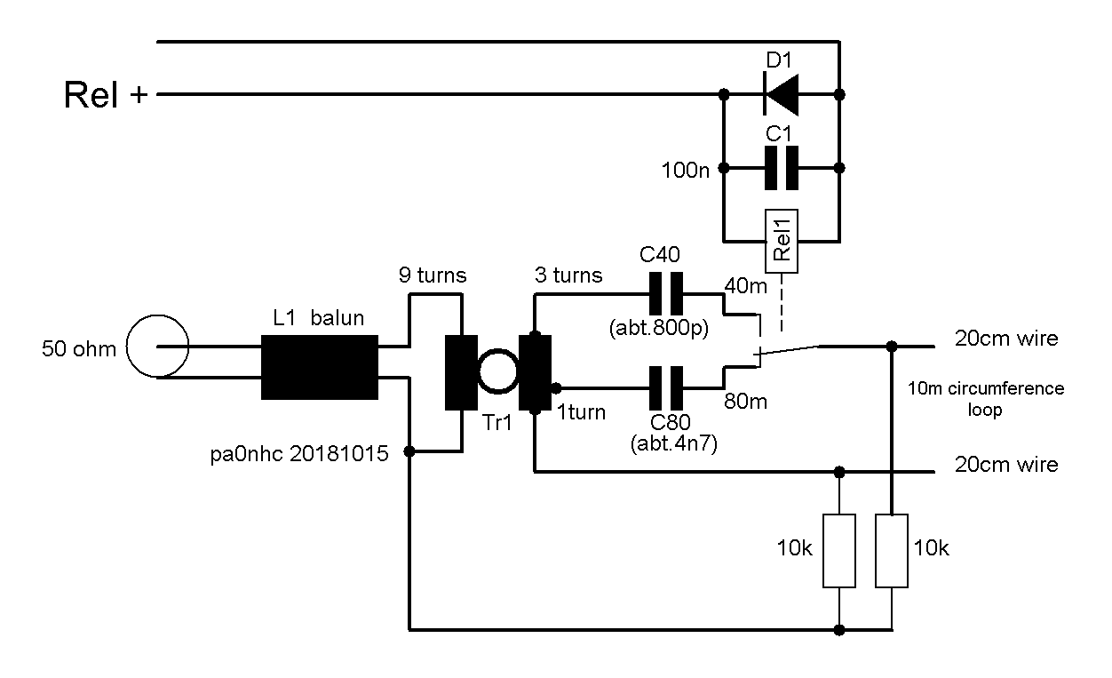
Wideband match, developed by pa0nhc.
|
After a lot of
experiments, the mismatch due to the transformers leakage inductance,
could completely be cancelled. |
My values for these series resonance capacitors are :
C80 => 4700 pF. Fres
with transformer wires abt. 3650 kHz.
C40 => 806 pF.
Fres with transformer wires abt. 7100 kHz.
You could use them as a guide when setting up your match box.
Capacitors :
With 400W power on 80m, 25.5 Arms runs in C80, and about 260Vrms (365Vp)
stands across C80..
Best use high voltage / high current SMD capacitors, or wired mica capacitors.
Use enough capacitors of equal value in parallel, to keep the RFcurrent
in each capacitor below capacitor specifications.
There is room enough for a large number SMD capacitors.
400V film or ceramic capacitors with low temperature coefficient are
useable to.
The new PCB is suited for all.
Heath losses.
After 10 minutes 100W continues power, the temperature rise in the transformer was
totally acceptable, and occurred mainly in the copper inside the core
hole in the secondary (highest current) winding.
The ferrite core did NOT show warming up. The insulation between the windings and the ferrite core was totally satisfying, as no arcing nor insulation weakening occurred.
Warning : MAXIMAL peak power on 80m is 400Wrms.