| << |
De-noising and
Grounding.
pa0nhc 20200611.
(C) The
use, publication, copy and modification of all info on this site is only
permitted for non-commercial
purposes, and thereby explicitly
mentioning my radio amateur call sign "PA0NHC", as the original
writer / designer / photographer /publisher. (C)
|
Blocking mains power noise.
Without measures, noises at the mains power lines,
and the safety ground lin enter the radio room,
Safety ground noises can be blocked by disconnecting the safety ground, and
connect all equipment in the radio room to a separate noise free, and low
inductance ground source.
One solution for blocking mains power line noises,
is the use of an "Ultra
Isolation Transformer". Such a transformer has a negligible small parasitic
coupling capacitance between primary and secondary windings, and/or a screen in
between. The noise coupling between primary and secondary transformer windings
is therefore very weak. The transformer iron core also damps high
frequency noise. The output is isolated from the input, reducing chances of
electrical shocks.
A cheaper solution is blocking mains power
line noise by a
good multi stage mains filter, and a noise free RF
ground. Read
details.
Coax cable noises.
Antenna cables can run near mains cables and noisy equipment. These noise
sources can induce noise currents into the common mode circuit of the antenna
feed cable (the outer skin of coax cable screening). Good Common Mode Chokes
("CMCs") will block these common mode noise currents. Noise currents
then cannot run
towards the antenna nor the radio, and will not be heard.
But CMCs can also prevent harmful common mode
circuit resonances.
Such resonance will amplify common mode
currents, causing :
- Distortion of the antenna radiation pattern ( antenna not anymore radiating maximaly
in the wanted direction).
- RF in the radio
room ("feed back" and "hot" radios),
- Amplified noise currents, stronger noise at certain frequencies. Read
details
Installing common mode chokes.
|
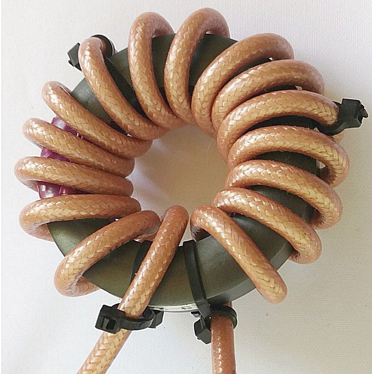
An optimal common mode choke for this antenna.
RG400 (5mm PTFE coax) wound 16 times through the hole of a 61mm dia mix 31 ferrite
core (that
equals 16 turns). ONLY
use FairRite catalog Nr 2631803802
This choke has a broad Hi-Z resonance around 4 MHz of upto 8000 Ohms
(!).
Good for 400W in a well balanced system.
See
how the begin and end of this slippery coax are fixed on to the core at
4 places with each two black nylon straps.
|
This way, all cable pieces and common mode chokes can be fabricated in
advance, and later on easily installed, or exchanged for repair.
At the top : a 100 Ohms bifilar (bi-wire) choke (wound with two PTFE
silver
plated wires in parallel).
Bi-filar chokes are perfectly balanced, and will work well in coax systems.
Influence of the short piece of 100 Ohm bi-wire on 50 Ohms VSWR is
negligible.
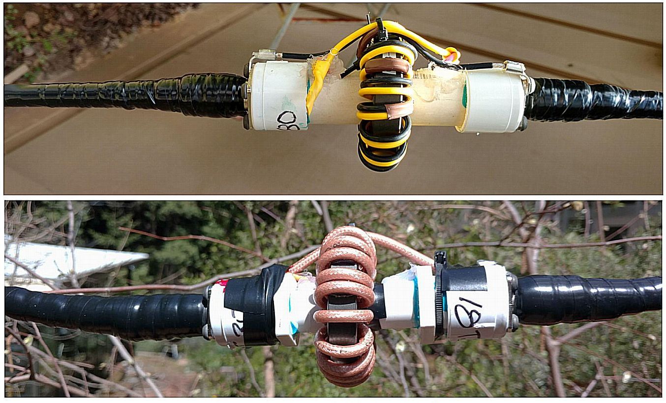
A 50 Ohms coax CMC, also connected in between two pieces of 50 Ohms coax
transmission line.
Both CMCs are put over
short pieces of PPC pipe with N-female
busses.
Prevent water intrusion in coaxes and thereby ruining them !
- All connections are made by the use of water tight N-connectors
and busses,
and are water protected with vulcanizing butyl tape. |
Start
installing CMCs at both antenna and transmitter.
REM : In the matchbox at the top of the loop, a CMC is already installed.
For this
antenna extra chokes should be installed in between at
intervals of maximal 10m.
IN GENERAL : At feeders with lengths
for the highest working
frequency of 3/8
lambda or more,
CMCs should be installed at the coax feeder at maximal intervals of 1/4 lambda.
My grounding system.
 Our large atrium steel
construction is connected to the earth via steel reinforcements in walls and pillars.
Our large atrium steel
construction is connected to the earth via steel reinforcements in walls and pillars.
It showed to be the best "ground" in my location.
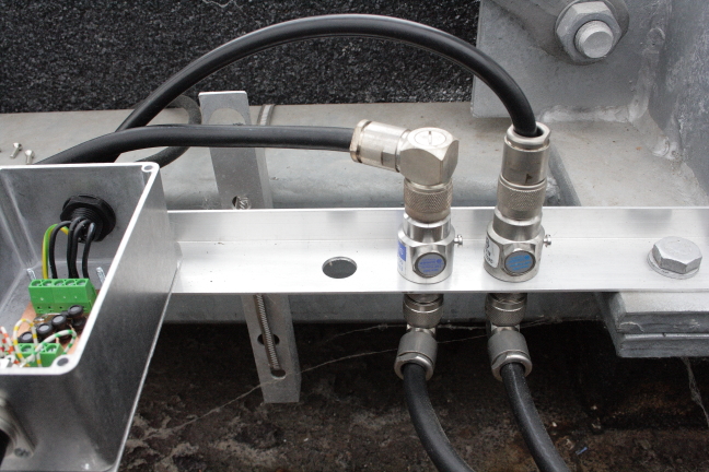
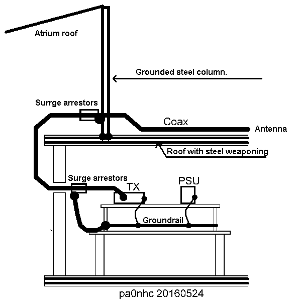 The coax lines are connected
via surge arresters, and an aluminum L profile, to this steel atrium
construction.
The coax lines are connected
via surge arresters, and an aluminum L profile, to this steel atrium
construction.
REM: the correct installation direction of the surge arrestors is important.
The separate box contains a second
noise filter for the tuning motor and relay lines,
protected by high speed bi-polar over voltage diodes, which short circuit
these lines in case of lightning nearby.
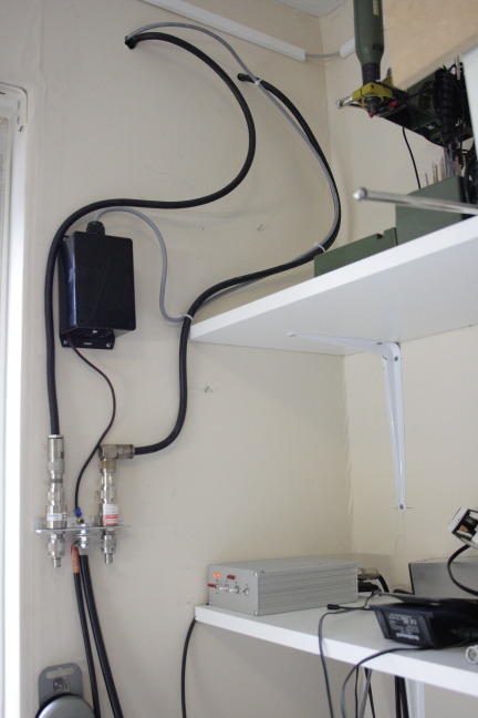 Then both HF and VHF coax cables, and the command line, enter
into the radio room through an insulating wall.
Then both HF and VHF coax cables, and the command line, enter
into the radio room through an insulating wall.
The black box contains a first relay and motor line filter.
The ends of the coax cables are again via surge arrestors connected to
an aluminum L-profile, which serves as a
central ground point for the radio room.
A thick cable connects the ground to
the ground rail on the back of the radio table.
The
mains power supply in the power cabinet contains ground leak switches. In an
advent of only a small harmless current difference between live and neutral of more than 30 mA,
power is quickly switched-off.
Mains ground can therefore be exchanged by a separate noise-free
RFground (that is the Atrium roof).
To prevent noises on the mains safety ground wire to enter the radios,
the "mains safety ground" for the radio room is disconnected. All
equipment is only connected to the noise free system ground via the ground rail.
In the radio room, all ground connections of radio and PC equipment are only connected to the steel roof
construction in the atrium.
The mains safety ground is not connected to prevent
import of mains related noises.
At the back of the radio table is an aluminum strip which functions ar
grounding rail. It is connected to the grounding point of the incoming coaxial
cables.
The length of the connection between the rail and the grounding point at the roof is as short as possible (a few meters).
Both measures are effective to achieve "cold" (RF-free) equipment
housings