|
Some secrets of
Common Mode Chokes revealed. |
| >> | FairRite Flyer : Cable Cores For EMI suppression. |
| >> |
CMCs, the influence of temperature changes. pa0nhc 20200530. |
| >> | The all important dipole-end CMC in my Cobra antenna. |
| >> | CMCs (and screening) make very high S/N possible in my wideband active receiving loop antenna. |
| >> | CMCs improve reception with every Miniwhip active wideband E-field receiving antenna. |
|
|
|
|
General rules :
|
A CMC (Common Mode
Choke) with dominant
resistive losses will always reduce common mode
currents,
At
least one CMC
should be installed directly near the antenna feed point |
|
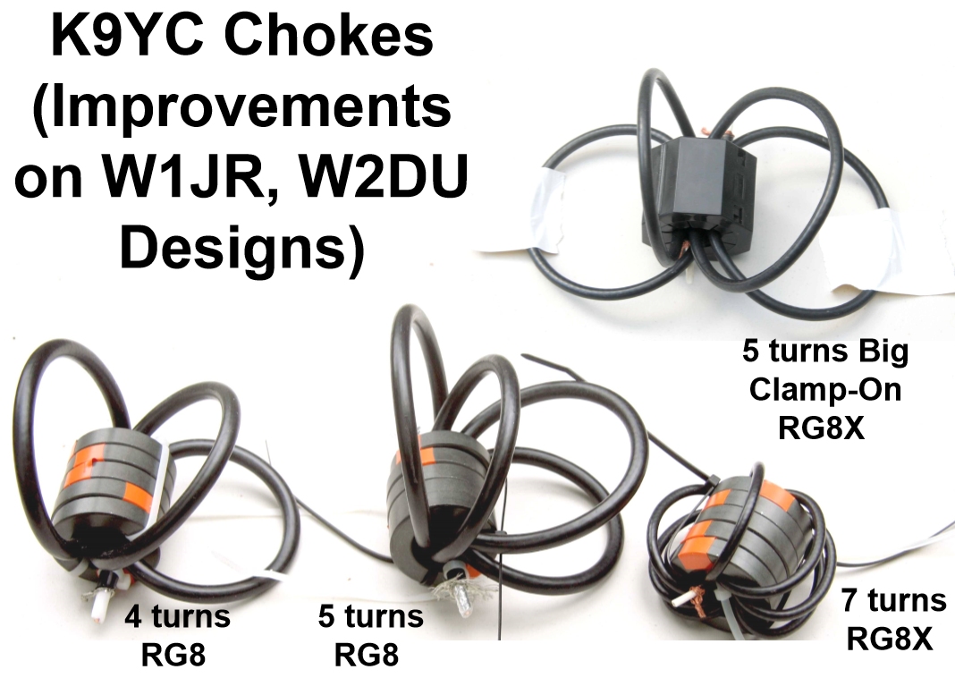
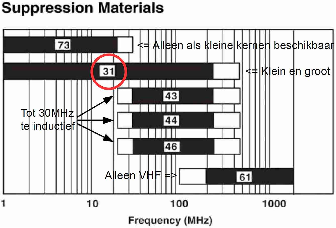
K9YC suggests the
use of Fair-Rite mix #31 cores. Buy cheap, buy
a larger number : |
The power of N2.
|
One 61mm #31 ferrite core with 10 turns 5mm coax cost 4.40 Euro. Here is why : More turns => far less current => (far x far) less temperature rise in the CMC core. |
CMCs in receiving systems.
Small receiving CMCs or
transformers. |
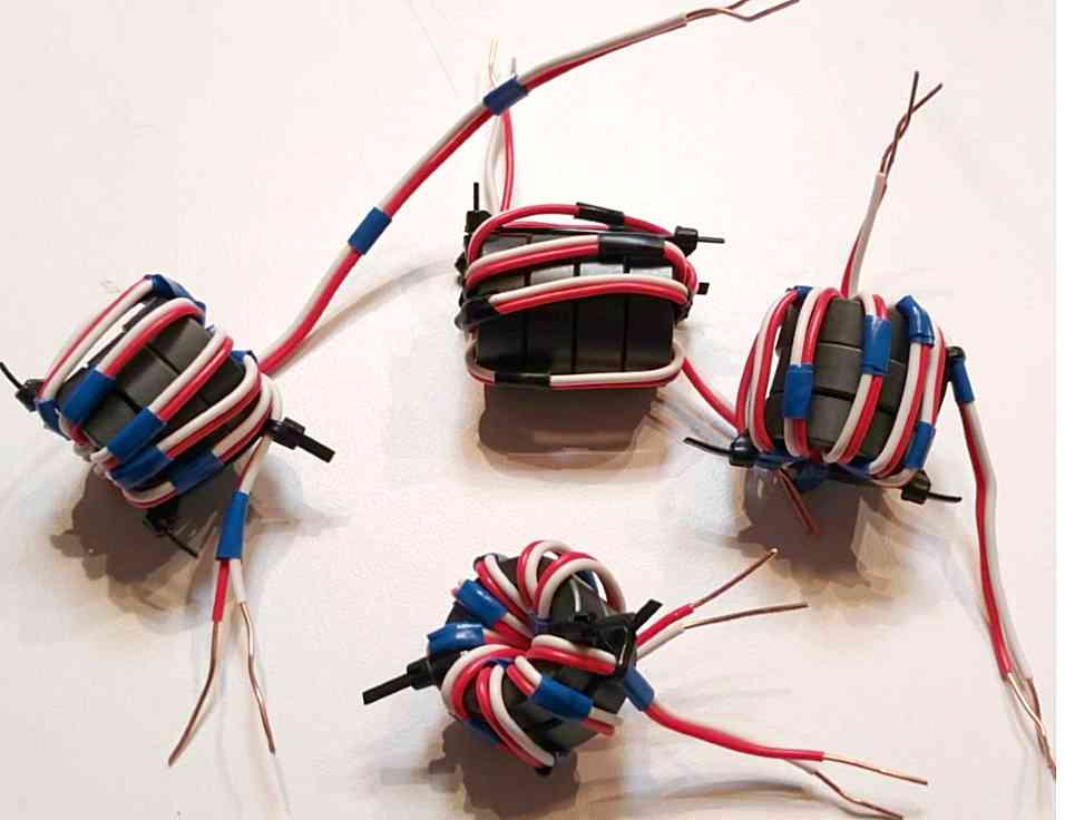
In receiving
systems are also transformers and CMCs used to suppress noise currents. Small
and cheap #31 cores (13x13mm, 26 31
48 00 02) can be used to construct very effective CMCs. Thin wire (0.25mm lacquered coil wire),
or a twisted pair retrieved from an UTP cable can be used.
#31 ferrite is conducting. To prevent damage to the insulation of lacquered coil
wire, these small cores must FIRST be insulated with 2 layers transparent
nail lacquer. A short circuit between wire and core results in a useless
coil, which is difficult to detect afterwards. Measure the insulation
between wires and core before installing the coil into the circuit.
See : http://k9yc.com/RXChokesTransformers.pdf
and pa0nhc
Active RXloop antenna
CMCs in transmitting systems.
|
|
K9YC
describes in http://k9yc.com/630MTXChokes.pdf
why CMCs should be used in transmit antenna systems.
K9YC advises at least 5 kOhm resistive
choke impedance.
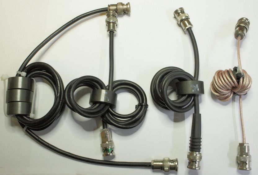
For short wave frequencies (2-30 MHz) only use ferrite material #31.
As most used coax vary in thickness between 5mm and 11mm, and for
instance 7 turns are needed, #31 cores with large holes are to be used.
For instance :
29mm core with 19mm hole 26 31 80 12 02
50mm core with 25mm hole 26 31 62 62 02
61mm core with 35mm hole 26 31 80 38 02
101mm core with 76mm hole 26 31 81 40 02
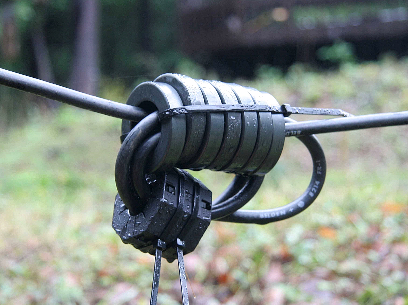
At least one CMC
should be installed over the feeder directly near the antenna feed point (near
the center of a
symmetrical dipole).
Problems by feed lines of 1/2 lambda length.
Due to 1/2 lambda resonance, feed lines having a length of 1/2 lambda (or a multiple : 1, 1.5, 2, 2.5 lambda etc.) will generate strong common mode currents in its center, and very high voltages on its ends.
While receiving, 1/2 lambda feeder resonance can cause strong amplified noises received at all 1/2 lambda feeder resonance frequencies. See : pa0nhc Active RXloop antenna
As damping of common mode currents is practically
impossible, two measures are possible against 1/2 lambda feeder resonance :
1. Change the length of the feeder,
and/or
2. Install CMCs on the feeder.
Start at the antenna feed point,
and install CMCs over the feeder at distances of 1/4 lambda or
less.
In a broadband receiving antenna systems (like my 0-30MHz, 1m dia. active receiving loop) all feeder resonance should be de-tuned to a higher frequency OUTSIDE the used frequency range, that is above 30 MHz. Install the first CMC directly under the antenna, and the last CMC directly near the power/RF combiner. Then fill the rest of the feeder length with CMCs at max. 3m distances.
Antenna unbalance.
Antenna unbalance results in :
- Strong common mode currents.
- High common mode voltages.
- Heating of CMCs.
- Radiation of RF in the radio room and houses.
- RF feedback in microphones.
- Receiving stronger noises from nearby.
- Deformation of the antenna radiation pattern.
Antennas which are know for their unbalance and over-heathed CMCs are : FD3, FD4, end-fed, inverted V.
Unbalance can also be caused by the capacitance introduced by nearby conducting objects, close to one half of the antenna. For instance other antennas, towers, masts, trees.
In a well
balanced antenna system, the ferrite core of a good constructed CMC remains cold.
Only the COPPER WIRE inside the hole of the core can show some temperature rise.
|
|
Maximal allowed power.
In well matched and well balanced
antenna systems, in good CMC's (Z>5kOhms) little heath will be generated.
As long as the common mode voltage over, and the common mode current through the
CMC, are small.
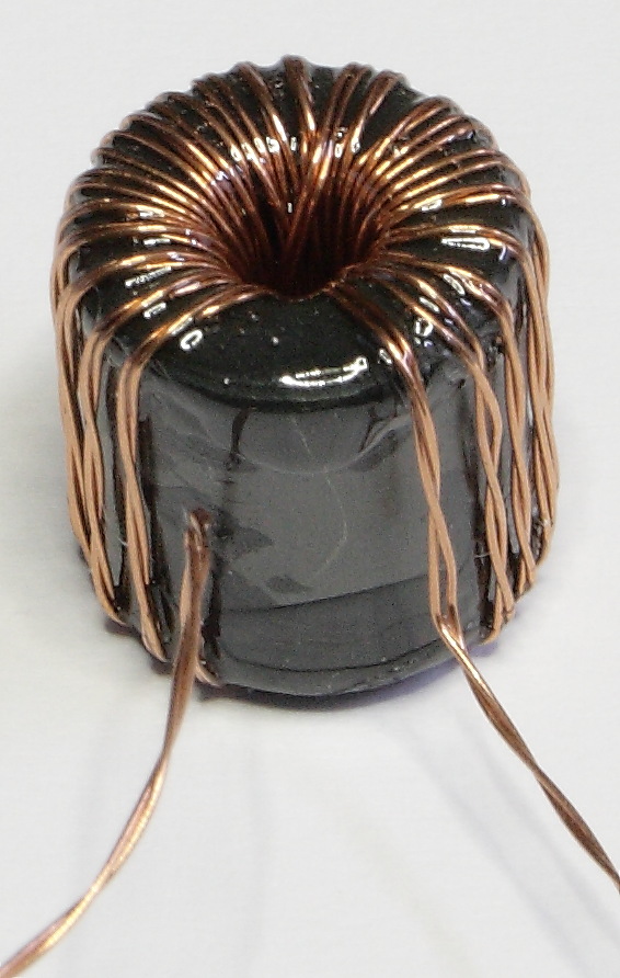
One coax choke is good for 100W. An air cooled bi-filar CMC can handle 800W ! ===>>
For larger power levels : connect CMCs in series.
When connnecting two schokes in series :
- The total choke-Z will be twice as large.
- The choke current will be twice as low.
- The heath developed over these two chokes will be 4x smaller
(P = I x I x Z = 1/2 x 1/2 x Z = 1/4 x Z)
- This heath will be divided over the two chokes.
- Each single choke will therefore develop 1/8 amount of heath.
- The allowed max. power will be up to 8x larger.
- The -3dB bandwidth of the choke combination will be abt. 2x wider.
- The antenna will therefore be useful over more frequency bands.
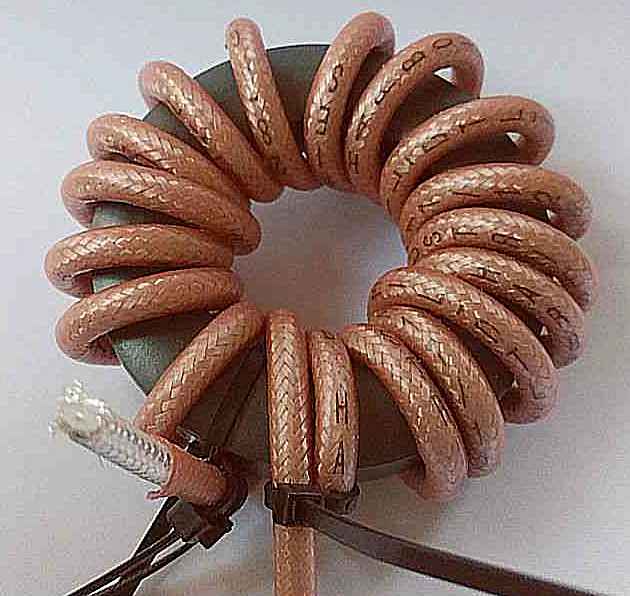
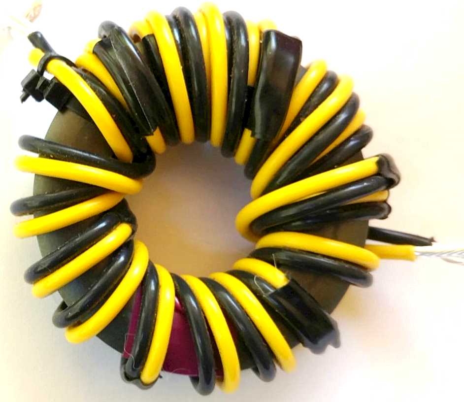
Choke winding tips.
When winding bifilar
(two wire) chokes :
Twisting of the wires is not allowed.
Wind both wires
close together and in parallel.
Use different colored PTFE wire.
When winding bi-filar and coax chokes :
Wind in ONE direction around the core, do not
wind backwards.
Each turn should lay beside another, not
running under or over another turn.
Some background theory.
SKIN effect.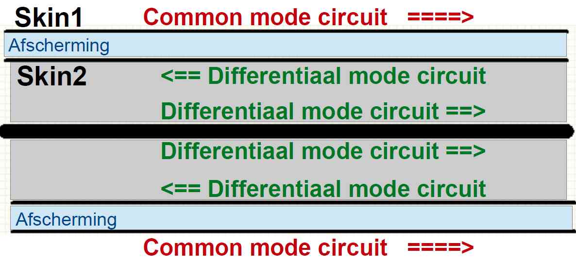 The
conducting screening of a coax cable is divided by the "Skin effect" in two RF
conducting layers.
The
conducting screening of a coax cable is divided by the "Skin effect" in two RF
conducting layers.
These layers are VERY thin (some thousandths of a mm.).
Both skin layers are therefore isolated from each other for RF energy .
A ferrite Common Mode Choke (CMC)
over the coax can only influence the OUTSIDE of the screening.
The first skin is inside the coax screening (the differential circuit).
The transport of energy between transmitter and antenna takes place here..
A second layer is at the outside of the screening (the common
mode circuit).
This layer caries RF signals (and noises) picked up from surroundings, and RF
picked up from the connected antenna.
Common mode current is bad.
Common mode current result into :
- Radiating transmission lines.
- Deformed antenna radiation pattern.
- Receiving of noises from surroundings by the feeder line.
- RF in the radio room.
- RF feedback in microphones.
- RF in the house.
- RF in the houses of neighbors.
How a Common Mode Choke (CMC) works :
 The CMC impedance consists of a series circuit of (induction +
capacitance + loss resistance).
The CMC impedance consists of a series circuit of (induction +
capacitance + loss resistance).
A good CMC shows a lot of loss resistance, which will be inserted
in series with the common mode circuit
(the OUTER skin of the coax
screening)
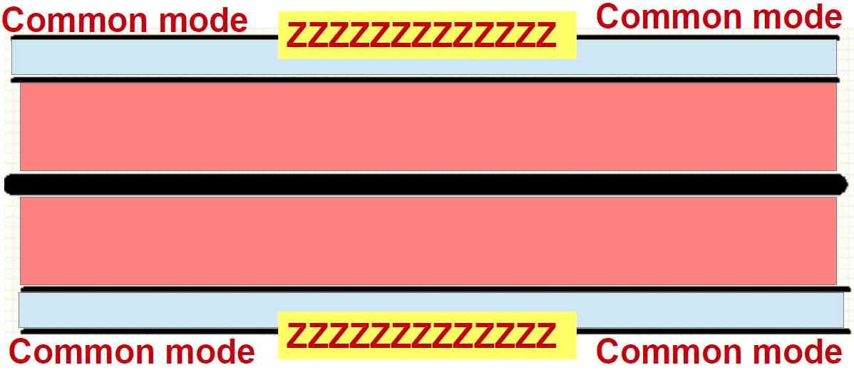
Imagine that, at the
location of the ferrite choke, the outer skin will be broken u
into two insulated parts. And the "loss resistor" "Z"
is inserted in-between.
The higher the "loss
resistance" of a CMC,
the better the reduction of common mode RF current and voltage.
This "loss resistor" weakens the RF common mode
currents, and RF voltage on cable ends.
A good CMC reduces common mode currents and voltages vastly, and over a wide frequency range.
Why not every ferrite mix performs well in a CMC.
|
Facts : If at the location of the CMC the
common mode impedance is
inductive, A choke which "Z" is dominant RESISTIVE, will always weaken common mode currents. |
|
 |