|
|
|
pa0nhc RF watt meter |
(C)
The use, copy and modification of all info on this site is
only permitted for non-commercial purposes, and
thereby explicitly mentioning my radio amateur call sign "PA0NHC" as
the original writer / designer / photographer / publisher.
The PCB is available.
|
|
Properties.
This sensitive active analog thru
- line meter system
indicates rms RF power,
connected to a transmitter and an external 50 Ohms load.
It measures the voltage
on the thru-line, and has a wide measuring range : 57 dB, from - 4 dBm to +53 dBm (0.4 mW to 200
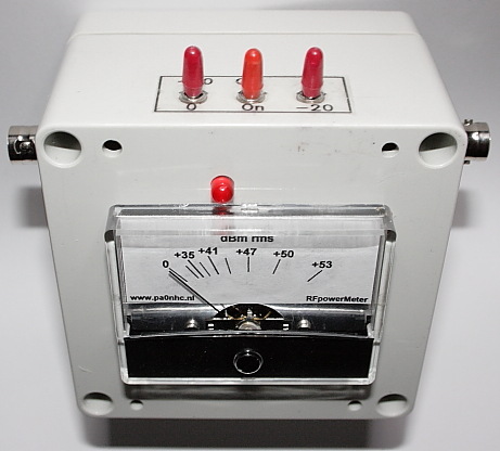
W). The meter scale is in dBm :
| s1 | s2 | Min. measurable | Max. readable |
| -20 | -20 |
0,41 mW = -4 dBm |
2,1 mW = +13 dBm |
| 0 | -20 | 1,98 W = +33 dBm | |
| -20 | 0 | 2,1 W = +33 dBm | |
| 0 | 0 | 198 W = + 53 dBm |
The expected useable frequency
range is 160 kHz to 145 MHz.
Easily extendable down wards to 16kHz or even lower if needed.
Power supply is 4 V to 5V, from 3x AAA battery at 3 to 8 mA load, with at least 25 hours battery life.
As long as the stated components are used, is the circuit free of adjustments, and works immediately. Inaccuracy due to the use of standard component values is estimated to be less than +- 1dB.
An easy to implement dBm meter scale is given below. All resistors and capacitors are low cost, low inductance SMD 1206 types.
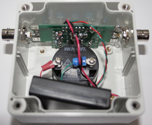
The PCB is specially designed to RF technique, with longer soldering islands
for easier heating, easier solder flow, and less component heating.
The miniature toggle switches are chosen for their
small size and low cost. REM : The switches need to have 4.14 mm pin
pitch to fit into the PCB.
If a meter is used with different internal resistance, R4,5,6 have to be adapted for full scale deflection at 3.3Vdc and 0.33Vdc IC output.
Please do print the PDFs and read them fully BEFORE you start soldering or drilling.
1. Save the PDF files
below to HDD (click-right - "Save target as ....")
2. Open the file from HDD in ADOBE READER https://get.adobe.com/nl/reader/
3. Print the file at A4 paper with setting "Scale
100%".
3. Keep the
prints as documentation for building and service of this
project.
| Schematic | Operation | Parts list | Soldering strategy | Meter scale | Switch panel |
| Meter scale table | Housing | Drilling sketch 1 | Drilling sketch 2 | Drilling sketch 3 | Assembling |
Testing.
Insert batteries.
Near the battery location, stick some plastic foam into the lid. It should gently clamp the battery holder in
place when the box is closed.
Close the box.
Set SW1 and SW2 both in un-sensitive position "0".
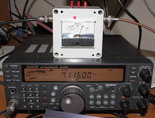
Connect a 50 Ohms dummy load and 100W RF power at 3.65 MHz.
The meter needle should point out +50 dBm.
 |
 |