 Evening twilight viewed from my living room window. << A multiband "End-Fed" antenna with a highly effective "wireless ground." Dv 20260923. Copyright pa0nhc. This text was translated from Dutch to English by Google Translate. I made this page using Expression4 software. |
 The new antenna.
In July 2025, at the age of 86, I moved from De Meern to Vleuten. Back pain. Heart failure. I can no longer stand unsupported and require a lot of assistance, as I have lost my sense of balance. So, I moved from a second-floor apartment to a ground-floor care residence. I went from a perfectly functioning 80m/40m magnetic loop antenna to an end-fed wire strung between trees. I feared the worst regarding interference.
The wire.
Why make things complicated when there is an easier way? That is why I bought an 80m-to-10m end-fed antenna kit from "HF-Kkits." It was a very complete package, excellent quality, and well-priced. My grandson
 Brian
did all the climbing and installation work.
Brian
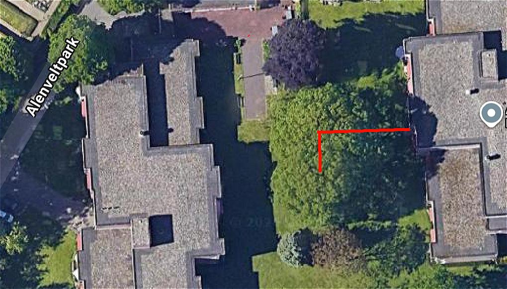
did all the climbing and installation work.The antenna starts at a height of 3 meters and rises westward to an oak tree at a height of approximately 8 meters. This section is about 18 meters long. The wire then descends southward to another oak tree at a height of about 6 meters. The loading coil for the 80-meter band is located in this section.
The antenna location is: 52.104213, 5.016324.
Lightning.
Experience has taught me that a lightning strike 100 meters away can induce massive currents or voltages in the antenna. About 40 years ago, this resulted in arcing from my wire antenna (spanning just centimeters). More recently, it caused a failure in a "Magloop" antenna. Large induced currents in the loop caused the 2kV film capacitors or the toroidal core to fail, rendering the loop untunable.
To best protect any transceiver that might be connected, I have installed a 350V peak gas-discharge surge arrestor between the transformer and the coaxial cable. I also use a switch capable of disconnecting both the coax shield and the center conductor, featuring at least 3kV isolation. However, if necessary, I certainly also disconnect the antenna lead at the transceiver itself.
The transformer.
This transforms the 50-ohm coaxial cable impedance to an antenna impedance of 2450 ohms. The transformer's primary winding consists of 2 turns, and the secondary winding has 14 turns, wound on a 62mm #61 ferrite toroid. One end of each winding is "grounded" to the common ground of the 50-ohm connection; consequently, static charges on the antenna drain safely to ground through the transformer.
 The unique feature of my antenna system: the "ground
frame."
The unique feature of my antenna system: the "ground
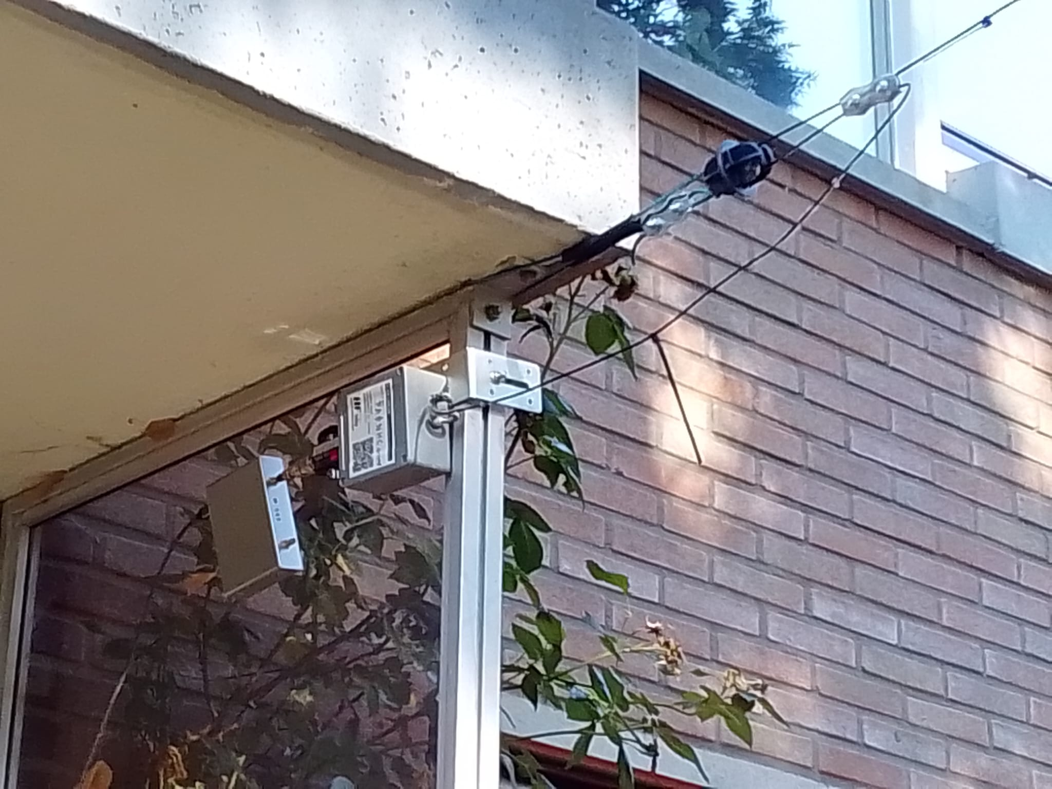
frame."An end-fed antenna requires a point of low system impedance ("ground") to feed RF voltage to one end of the antenna wire; the other end remains unconnected. The necessary short, heavy-gauge "ground" connection is often missing. Operators frequently use multiple quarter-wave wire segments tuned to amateur bands—known as radials—or even improperly use the coaxial cable shield for this purpose. ...resulting in interference-related problems.
The shield of my transmission line coax is connected to a vertical aluminum window frame at the transformer (see photo). That "frame" is screwed into metal threaded inserts located in both the ceiling and the floor. During construction, these inserts were welded to the (hidden) reinforcing steel. This reinforcing steel is, in turn, connected to the earth via grounding electrodes. The entire assembly forms a short, low-impedance connection to ground. For the (relatively long) radio wavelengths ranging from 80 to 10 meters, all the metal in those balconies (see photo at the top) acts as a broad, vertical, and well-grounded metal grid or "frame." My connection point on that frame thus serves as a very low-impedance point. That is my "Ground Point."
The antenna RF current.
The RF antenna current flows from the end of the transformer's secondary winding, via the antenna—which is strung perpendicular to the building—through the air to the ground. The RF current then travels through the ground to that 3-meter-long vertical aluminum window frame on my balcony, and from there, it flows back to the start of the transformer's secondary winding. Consequently, the RF current flows primarily in a vertical direction—or perpendicular to—the building's façade. As a result, there is little risk of RF current coupling into the horizontal metalwork of the balconies. Furthermore, these metal balcony frames shield the building from the high-frequency field. The result: No RF interference is noticeable in my PC setup (with audio mixer and external active speakers) or in my TV setup (with external active speakers). What I expected to be a disappointing experiment turned out to be a remarkably good antenna.
 Common-mode currents and CMCs.
Every coaxial cable has three (yes, three) surfaces along which current can flow. First, current flows along the center conductor from a source to a load. However, that same current then returns to the source along the inner surface of the shield. The coaxial shield, however, has a second conductive layer on its outer surface. These two layers are separated from each other by the "skin effect."
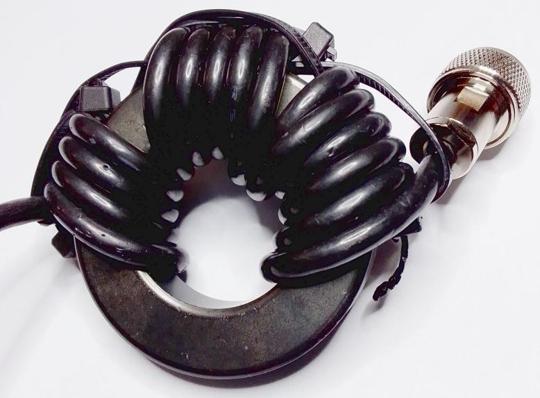
External RF fields can also induce RF currents on that outer surface. These are known as "shield currents" (or "mantle currents"). This interaction can cause highly troublesome effects. Therefore, shield currents must be avoided here—for instance, by using "common mode chokes" (CMCs). These create high blocking impedances specifically on the outer surface of the coaxial shield. The interior of the coaxial cable is isolated from the CMC's shielding effect, so the CMC has no influence on the signal inside. Difficult? Expensive? Highly effective CMCs are cheapest to build yourself. My homemade wideband CMCs consist of 13 turns of RG58CU Mil-spec C17 coax (approx. 1.2 meters in length) wound onto an FT240-31 ferrite core. See the photo on the right.
The coaxial cable windings must be wound tightly, side-by-side (not overlapping), and in a single direction.
Also, keep the ends of the coax as far apart as possible to limit parallel capacitance and avoid unfavorable parallel resonance.
Secure the ends to the ferrite core using black cable ties.
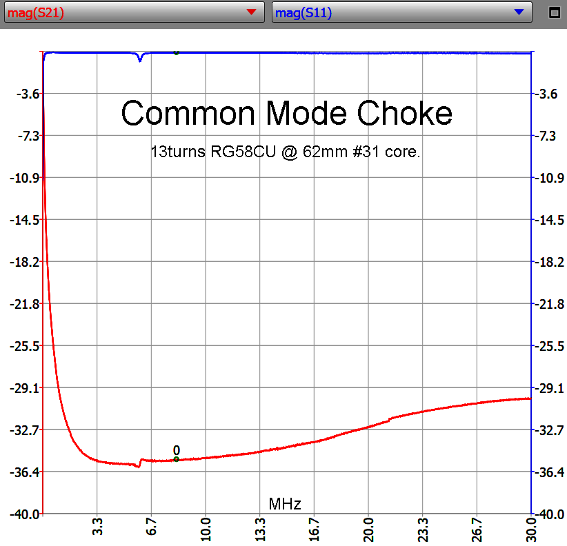 The blocking impedance of these CMCs, measured using a
VNA, ranges from 1600 ohms to 3100 ohms across the
entire shortwave band! See the graph alongside.
The blocking impedance of these CMCs, measured using a
VNA, ranges from 1600 ohms to 3100 ohms across the
entire shortwave band! See the graph alongside.Note: This type of CMC works best in locations with low source or load impedances. Therefore, do not connect it directly to a high-impedance end-fed wire; instead, connect it to the grounded, low-impedance input of the matching transformer.
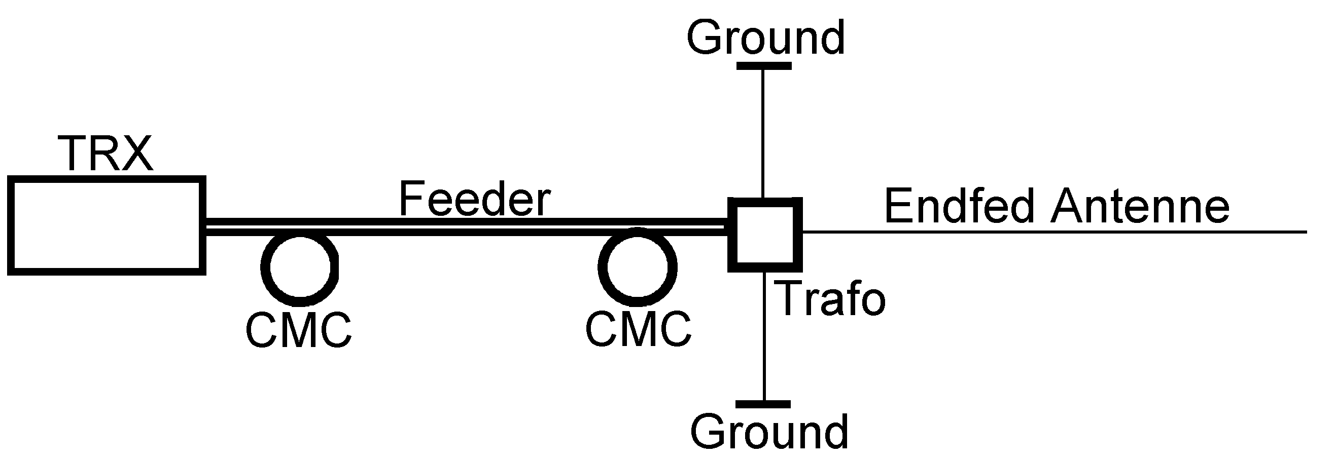
In my antenna setup, an identical CMC is installed between the matching transformer and the coaxial cable ("feeder"). The common-mode (HF) currents flowing along the outside of the feeder encounter significant resistance (attenuation) due to that CMC. Consequently, the remaining current easily drains away to the low-impedance "ground point." It can barely reach the transformer. An identical CMC is placed between the coaxial feeder and the transmitter, where it also blocks any potential shield currents.
However, the most important effect is this: the two CMCs also prevent the coaxial shield from acting as a "radial," which would otherwise degrade the antenna's performance and potentially lead to the pickup of interference. These CMCs prove highly effective in my antenna system. In my situation, the highly desirable results are:
+ Broadband low VSWR on all bands,
+ No HF interference in my room.
Coaxial velocity factor and the effect of CMCs.
For HF currents, the inside of my feeder effectively appears to be 50% longer than the outside—meaning approximately 21 meters instead of about 14 meters.
I simply refer to this apparent internal length for HF current as the "electrical length."
This "electrical length" effect arises from the presence of plastic insulation between the coaxial cable's center conductor and the shield.
As a result, HF currents on the inside of the coax travel 1.5 times slower than HF currents on the outer surface of the shield.
Traveling 1.5 times slower is equivalent to traveling at 0.66 times the speed. In English, this "0.66" figure is known as the coax's velocity factor. For RG58CU coax, it is 0.66; for PTFE coax, it can be 0.82 or 0.69. The length of coaxial cable used to construct both CMCs contributes to the path length traveled by the internal RF currents.
However, those CMC coaxial sections do not contribute to the path length for external RF currents. After all, that current is blocked by the CMCs—that is their function. Furthermore, the velocity factor does not apply in this context.
Consequently, for RF currents, the external coaxial length between the two CMCs is much shorter (12 meters) than the internal electrical length (21 meters).
And—thanks to those CMCs—the outer surface of the coaxial cable does not resonate on the amateur bands.
Which coaxial cable and connectors to use.
+ The coaxial cable used for my antenna is RG58CU MIL-spec C17.
+ Its velocity factor is 0.66.
+ Use coaxial cable with a tightly braided copper shield.
+ Avoid coaxial cable with foil shielding. I experienced poor shield contact, incorrect impedance (around 63 Ohms), and high losses even at 1 MHz.
+ Use connectors with a compression nut (gland) that firmly clamps the coaxial shield.
+ With UHF and BNC connectors, ensure a tight, play-free fit.
+ Ensure they press firmly against each other after assembly to prevent signal leakage.
+ Use N-type connectors for outdoor applications; they are reliably waterproof and provide good contact.
+ High-quality BNC connectors may be used indoors, though they are not waterproof.
Antenna measurements.
The Vector Network Analyzer I used is a “NanoVNA V2.2 Plus4”. The software used was VNA-qt. In addition to its two RF ports, this VNA features a mechanically robust USB-B port. The required 5 V DC power was supplied to this port via a 5-meter-long data cable.
After shortening ("trimming") the antenna, resonance plots and impedance measurements were performed on the antenna.
The VNA was coupled directly to the antenna transformer.
The remaining measurements were performed with the VNA connected at the start of the feed line, with a CMC at both the transmitter end and the antenna end.
The optimal length of the coaxial feed line.
The total electrical length of the coaxial feed line—including connectors and CMCs—is crucial for achieving an optimally low VSWR at the transmitter.
This total electrical length odf the feeder must be 1/4 wavelength at 3.55 MHz.
Consequently, for 7.1 MHz the electrical length is 1/2 wavelength; for 14.2 MHz, 1 wavelength; for 21.3 MHz, 1.5 wavelengths; and for 28.4 MHz, 2 wavelengths.
At these electrical lengths, the feed line behaves as a multiple of a half-wavelength for all the aforementioned bands.
The objective is to ensure, that the VSWR seen at the transmitter, differs as little as possible from the VSWR measured at the antenna.
Calculation example.
The velocity factor of the cable used to construct a CMC was 0.66 (see photo).
When CMCs are made using this cable, each one effectively incorporates a specific length of coaxial cable.
The external (physical) length of that coaxial cable is only 0.66 times its (internal) electrical length.
The total physical feeder length for 3.55 MHz (including the physical coax lengths of both CMCs and the connectors) is then:
Speed of light / f x 1/4 x Velocity factor
300 / 3.55 x 1/4 x 0.66 = 13.94 meters.
This (total) physical feeder length serves as the basis for the coax length.
If, for example, 1.4 m of coax were used per CMC, the physical coax length between the two CMCs would be: 13.94 m - 1.4 m - 1.4 m = 11.14 meters.
Proof that a total physical feeder length of 13.94 m is the right choice for this antenna covering the 80m, 40m, 20m, 15m, and 10m bands :
To demonstrate the optimal effect of this most favorable electrical coaxial length, VSWR measurements were again performed at the transmitter end of the feeder.
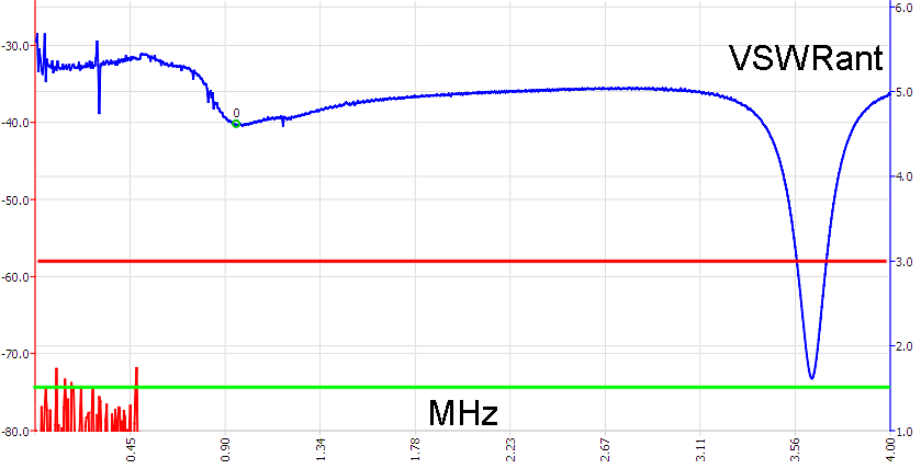
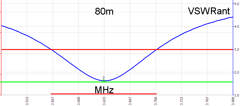
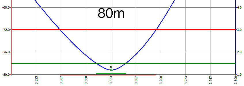
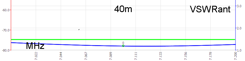
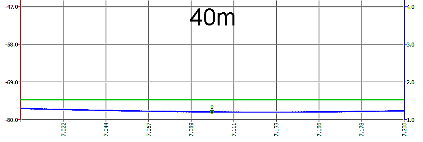
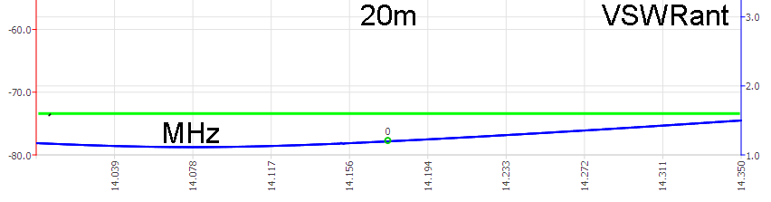
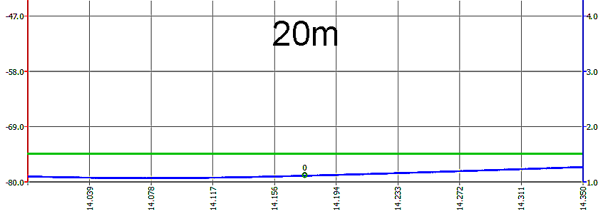
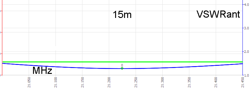
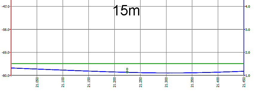
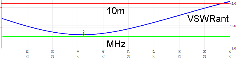
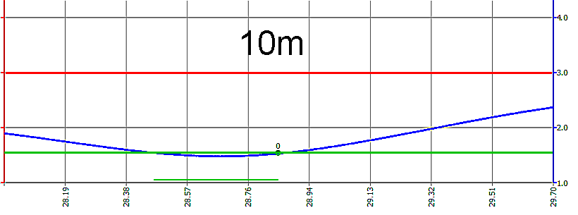
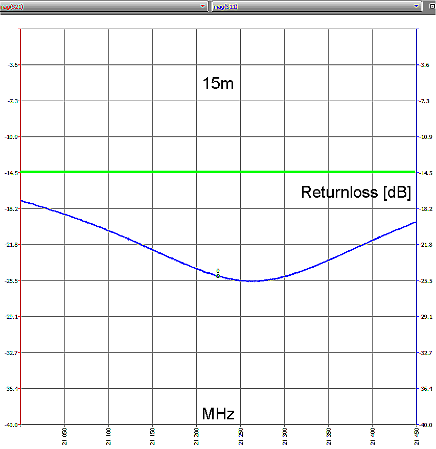
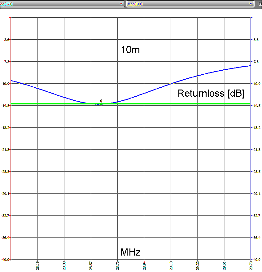
The VSWR values measured at the transmitter now roughly correspond, for each frequency band, to the VSWR values measured at the antenna. See graphs below.
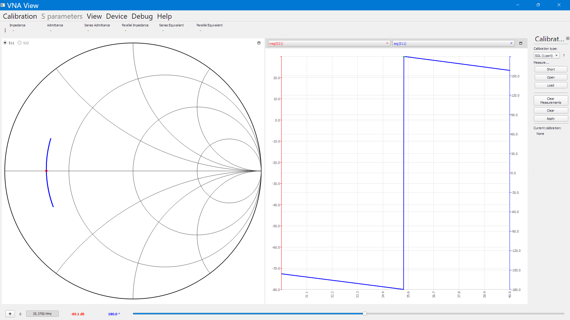 Easily measure
the exact length of any coaxial cable.
Easily measure
the exact length of any coaxial cable.What is the physical length L of the RG58CU coaxial cable used for the CMC shown in the photo above?
+ Connect one end of the coaxial cable to a VNA, but leave the other end open.
+ Display the phase characteristic of the coaxial cable.
The first phase jump of that cable (from +180 to -180 degrees) occurs at a frequency of 35.375 MHz.
See the adjacent image.
The electrical length Le of that coaxial cable is therefore 1/4 wavelength (lambda) at 35.375 MHz.
Le can then be calculated as: Le = (( c / f ) / 4 ) or ((300,000,000 / 35,375,000) / 4) = 2.12 m.
For that single CMC the physical coaxial cable length is then L = (Le × Vcoax) = L = (2.12 m × 0.66) = 1.4 m.
Too long or too short feeder ?
* If a calculated feeder length is longer than required, coil up the excess section. Keep feeder length as calculated.
* If a feeder length required to connect the transmitter to the antenna is longer than 11 meters, you must use double the total physical coax length :
2 x 13.94 m = 27.92 m. After that, agaian subtract the length of the 2 CMCs from this—for example: 27.92 m - 2.8 m = 25.12 m of coax. In that case, order 26 m of coax.
* When measuring this coax length (which is about twice as long), the first phase shift (including the two CMCs) should occur at a frequency that is half as high:
(3.55 MHz / 2)—i.e., at 1.775 MHz.
* Trim one coax-end carefully and measure again, until exactly at 1.775MHz the first phase shift occurs.
* The electrical length is then (27,92 / 0.66) = 42.3 meters. Which is 1/2 wavelength for the 80m band.
VSWR and the use of the internal automatic antenna tuner.
If the VSWR is lower than 1.5:1, the TS570-D's automatic tuner does not need to be used.
The reflected power is then less than 4%. If the VSWR rises unnoticed above 1.3:1, the transmitter automatically reduces its output power to minimize the risk of damage to the final stage.
The tuner may be used to bring the VSWR down to a safe level for the final stage, up to a ratio of 3:1.
The tuner must not be used if the VSWR exceeds 3:1, as this could damage the unit.
At that point, the reflected power is 50% or higher.
Initial practical experiences.
During the day, the noise level I receive on the 80m and 40m bands is very high—up to S9. It appears to originate from local sources of interference.
Usually, all local interference gradually disappears after dusk. The remaining background noise levels are then, for example, S5 on the 80m band and S2 on the 15m band. For an urban environment, this is undoubtedly a good result.
On the 10m band, the "man-made noise" is then only slightly stronger than the receiver's own internal noise floor.
July 2026: Amateur signals reaching up to S9+30dB were visible on the 80m band! The antenna seemed to perform well in an easterly direction, picking up signals from Germany, Ukraine, and Switzerland. Dutch amateurs reported good signal strengths considering my output of only 100W.
+ Amateur signals of S9+20dB were received on the 40m band.
+ DX signals were observed against very low noise levels on the 15m and 10m bands.
+ On 21 MHz, I made.earlier contacts with English (!) amateur stations. Signals were S9+ both ways, with minimal QSB. Shaun (M0BJL) told me at the time that I was producing the strongest signal he was receiving across the entire 21 MHz band. Evidently, there was exceptionally good "tropo propagation" at that moment.
This suggests that my antenna has a favorably low take-off angle towards the west on 21 MHz.
On September 7, 2026, at approximately 16:00 local time, I compared the signal strengths displayed by my TS570-D's S-meter with those from the Maasbree WebSDR.
For a few reasonably strong (S9 to S9+20 dB) amateur radio stations and beacons in the 40m, 20m, and 15m bands, the differences amounted to only a few dB.
The TS570-D pre-amp was switched off, and the S-meter had previously been calibrated on 80m. Even when suspended beneath those three large oak trees, this antenna performs well.
Noise.
The anenna is widebband, and has low VSWR over nearly 16MHz bandwidth (!).
The TS570-D receiver input circuit is wideband too.
All the wideband strong noise received by the antenna (from power switching apparatus and solar panels etc.) then addsup in the receiver input.
Then saturating the receiver input with strong wideband noise. Generating lots of extra noise.
On 160m, 80m, 40m and 20m i suffered from a unnatrually high noiselevels (up to S8/S9).
When switching the receiver attenuator to ON, not only all signals dropped 3 Spoints, but the noiselevel dropped far more.
This is an indication that the receiver-input circuit is overloaded by all these wideband noise sources.
In these circumstances :
+ Switch the receivers attenuator to ON,
+ After that also switch the receivers pre-amplifier to ON,
Then the signal strength indication and received noislevel are nearly normal again.
Overload gone => extra noise gone.
indicated by the SWRmeter of my TS-570-D.
(the electrical length of my coax feeder is 1/4lambda@3,5625 MHz).
| Band | VSWR <= 1,5:1 Use of tuner not needed |
VSWR <= 3:1 Use of tuner allowed |
|
80m 3.635 B=0.350 |
3.598-3.687 B=0.089 |
3.578
-3.735 B=0.157 |
|
40m 7.0-7.2 B=0.200 |
6.599-7.522 B=0.929 |
6.208-8.962 B=2.754 |
|
20m 14.0-14.35 B=0.350 |
13.320-14.710 B=1.390 |
12.625-16.805 B=4.180 |
|
15m 21.0-21.45 B=0.450 |
20.205-22.414 B=2.209 |
19.240-23.030 B=4.690 |
| 10m 28.0-29.7 B=1.700 |
27.250-29.650 B=2.400 |
25.775- ????? B> 4,225 |
The 80m band is usable between
3578kHz and 3735kHz.
(!!) On the whole of 40m, 20m, and 15m bands, you can transmit
without a tuner (!!)
And nearly the whole 10m band
can be used without a tuner.
Even the 160m band is usable between 1940kHz and 1970kHz,
Tested with a tuner and 10W output.
My signal strength was
S9 at websdr
Maasbree.
Above the RED
line, VSWR >= 3:1.
Below the GREEN
line, VSWR <= 1.5:1.
VSWR
measured at the antenna
VSWR measured at the transmitter-end of
the feeder.
 |
Compareds with the left side
column graphs. The VSWR at the TRX-end of the feeder is always better than on the antenna itself ! 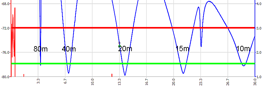 |
 |
 |
 |
 |
 |
 |
 |
 |
 |
 s s |
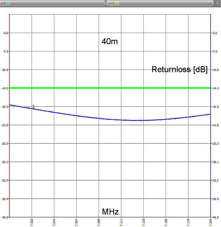
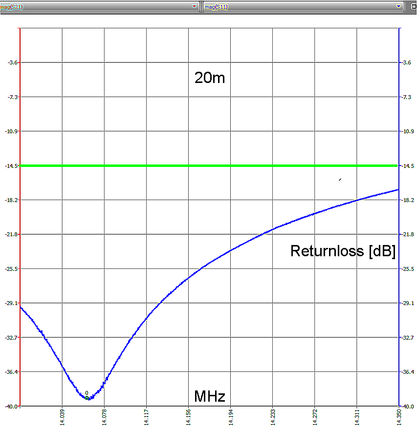
| Returnloss of the antenna. |
  |
  |
 |
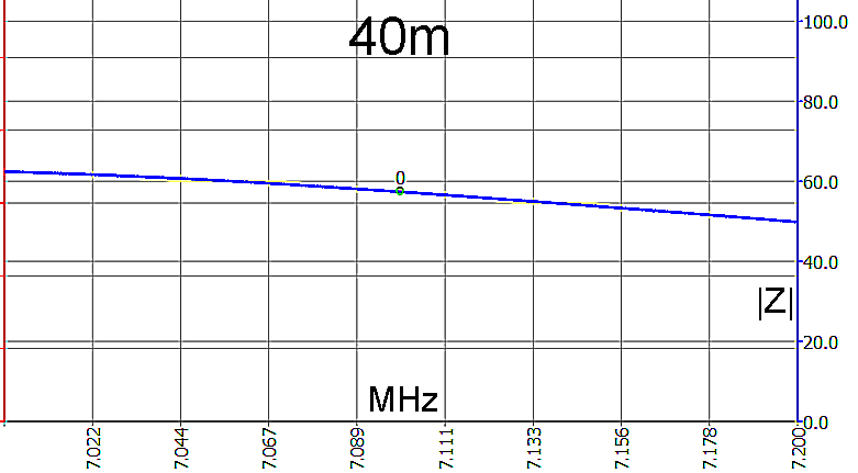
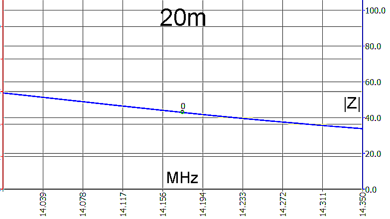
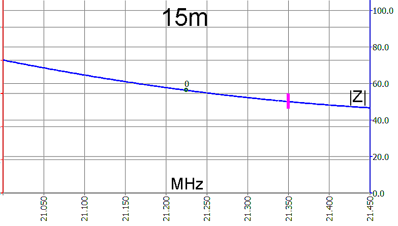
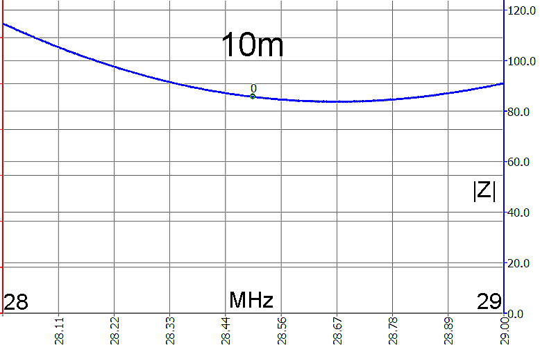
The antenna impedance. It is, except at 14MHz, a bit too high.
  |
  |