I am re-located.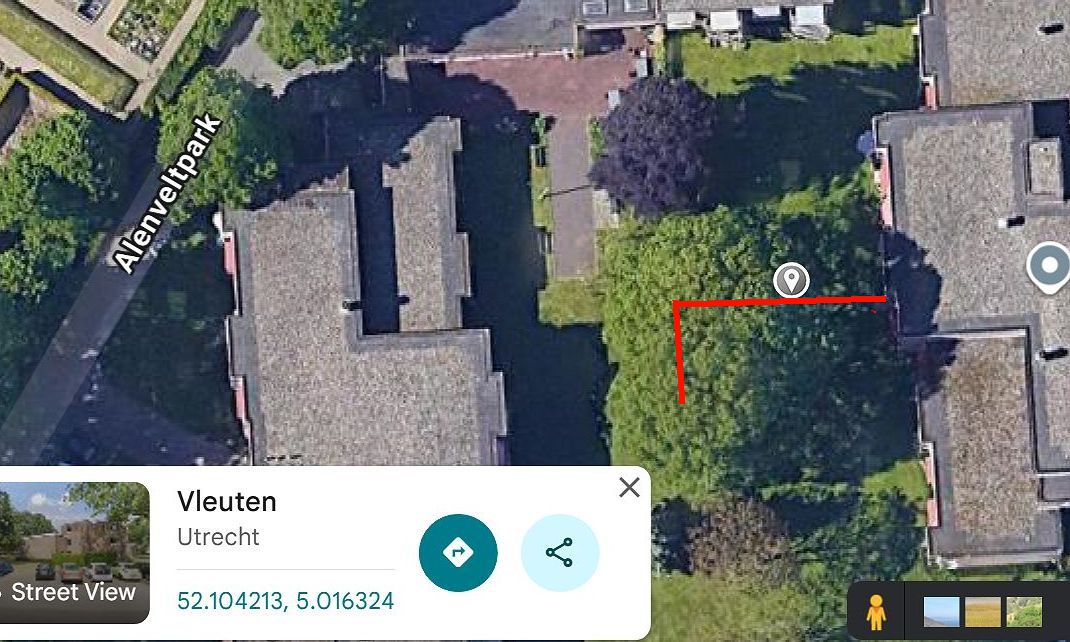 Coördinates of my antenna : 52.104213, 5.016324 . |
|
In 2025, at the age of 86 years, I moved to an elderly-people care facility in Vleuten (Utrecht-N). My spine is bad. But my brain is OK. My new antenna : So i needed a new antenna.The only way to install one in my new location was spanning a long wire. Going from my appartment to a first big oaktree, and from there at 90 degree angle to a second big oaktree (see photo). Feeding it with HFpower was only possible at the beginning of the wire. So the antenna became an "End Fed" antenna. I purchased at HFkits.nl the following DIY kit. End Fed 10/15/20/40/80m antenna kit and a common mode choeke kit 3-30MHz mantelstroom filter 800W. They were including coil parts, cabinets, hardware and a roll of special Kevlar antenna wire.The wire is made with silverplated copper braid as aconductor, and PVC outer insulation. Performances of my antenna : Today the antenne shows,when in resonace, very broadband low VSWR <1,5 at frequencies higher than 6 MHz. But these resonances are 4% to low in frequency. Resonance for the lowest band (80m) is even 12% to low. The antenna must be trimmed. Reception (may 2026). My first impression about received signals on 40m, 20m and 15m bands are good. Relatively stable S9 to S9+20dB signals for Russian- and a Kuwait stations on 20m and 15m. At the 40m band a regional Dutch station at 40km distance showed also S9+ on the calibrated S-meter. But during daylight, strong manmade noise is present on the 80m and 40m bands. Possibly caused by solarpanels. On 20m the manmade noise is less strong. The 15m band is completely noise-free. Building. I constructed the transformer and the common mode choke like instructed and shown in the very good instruction pages at the site of HFkits.nl .The coils must be constructed EXACTLY like on the photos.The 170 turns 80m-antenna coil was for me a bit difficult to wind by hand. I tried but was not staisfied wirh the result. So I purchased one somewhere else. Expensive. Installing. My grandson Brian (17 years) performed all the physical antenna installation work,using a long ladder. Thanks Brian ! The antenna starts at the side of my appartment with the transformer at only 3m height. Then it runs in direction West to 7m hight. After that running at an angle of 90 degrees to the South. Ending at 5m heigth. All contact surfaces on transformer, lightning arrestor, 80m coil, antenna wire ends, plugs and coax etc. were water protected using Vaseline. According to a groundwater charts from Rijkswaterstaat, the local ground waterlevel is not deep. This end fed antenna needs an artificial ground potential. The transformer input ground connenction is fitted with an external lightniing arrestor.From here the outside od the arrestor is directly connected to ALU window frames. These are screwed to the steel reïnforcement in the concrete of the roof of my balcony. The ALU window frames and the ALU balcony rails are interconnected. This total metal structure, forming an artificial ground, seems to be working very well. Trimming. Cut only short pieces off wire, then check resonance frequencies. 1. The long part of both antenna wires must be shortened to tune the antenna to 40m, 20m 15m and 10m bands.Try again until the result is OK. 2. After that, the short piece of antennawire, must carefully be shortened for the wanted 80m resonance. The "VSWR <1.5" bandwidth on 80m will be narrow, maybe only 60kHz. . ------------------- |