 |
 |
 |
| << |
Pa0nhc WebSDR muter.
Copyright. |
A simple hardware circuit silencing webSDR
sound in a small
ABS die cast ALU box.
Connects to a TRX or PA, PC audio, headphone and active speaker.
RF filtered connections.
Settable key line input for transmit high/low.
Settable key line bias pull up/open/pull down.
Audio output and mute switch able on/off.
Including an internal, linear, rattle free power supply.
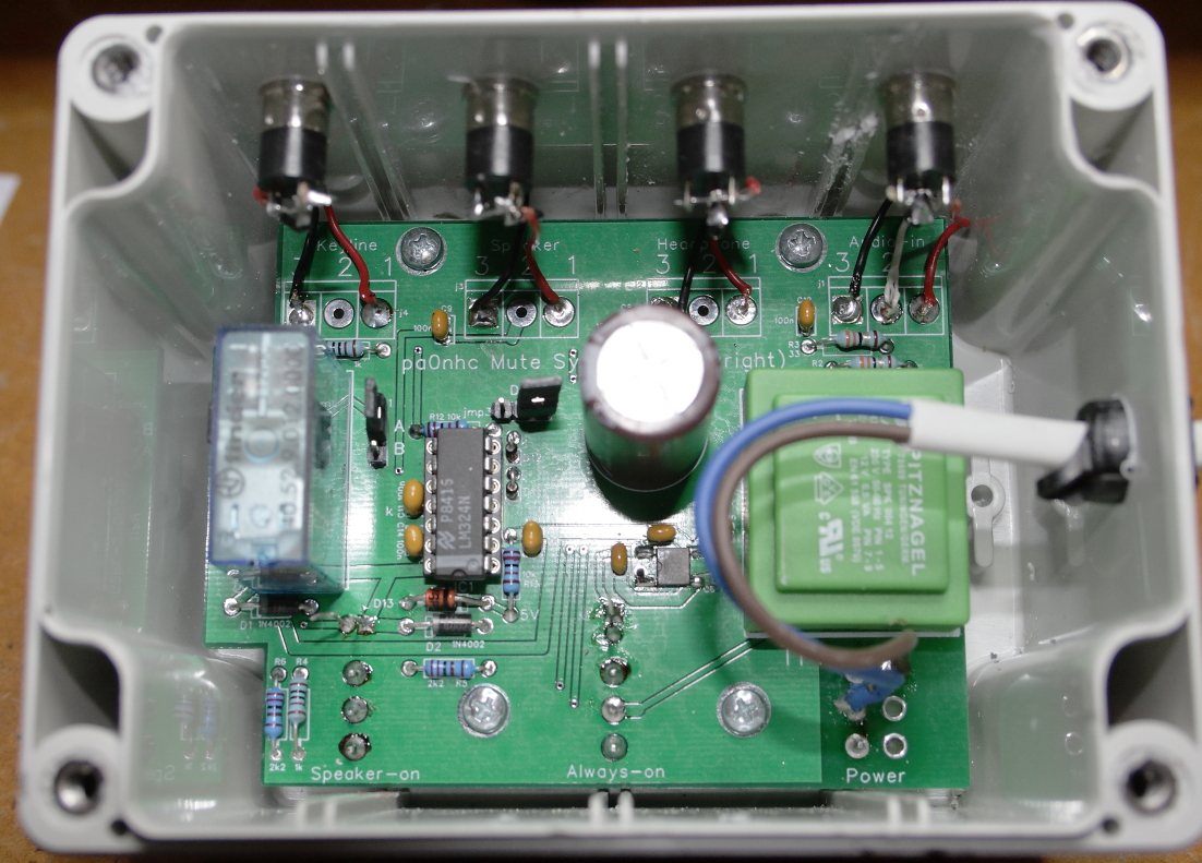
I now present version 2. The relay is now
powered by an IC LM324N in stead of a bi polar transistor.
The IC forces
its output to GND or +, resulting in a positive shutting down of
the relay, and LED2.
Not only the relay output, but the bias for the IC is now also changeable to
personal needs.
|
|
|
|
|
|
Component
list 20210521 |
Click-right on a picture to copy it.
|
|
|
|
|
|
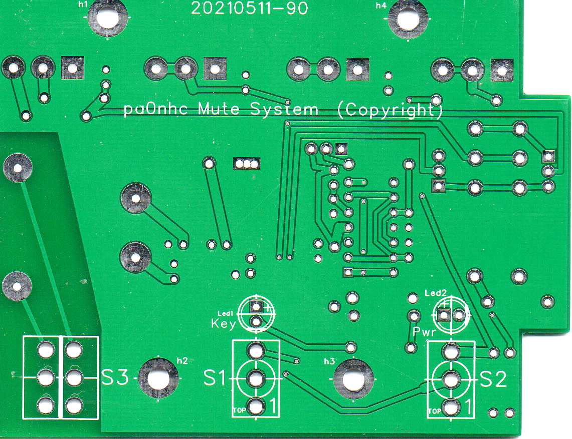
This PCB is available.
Purpose.
More and more amateurs suffer from strong QRM, preventing them to receive weaker
signals.
A solution for comfortably listening to other radio
stations, is the use of a to the internet connected PC, and a low noise "WebSDR"
(like "Maasbree" http://websdrmaasbree.hamshack.info:8901/
). The drawback is that the listeners own transmitted signal
will also be heard, creating annoying echoing.
When starting to transmit, the received PC-audio should therefore be muted (silenced). When using a modern TRX with appropriate data connections, "CATSinc" software can do that for you.
But in some cases, the use of software is not possible, or wanted. Then this hardware circuit can silence the audio from a PC (WebSDR) for you with nearly no latency. It is a nice little building project.
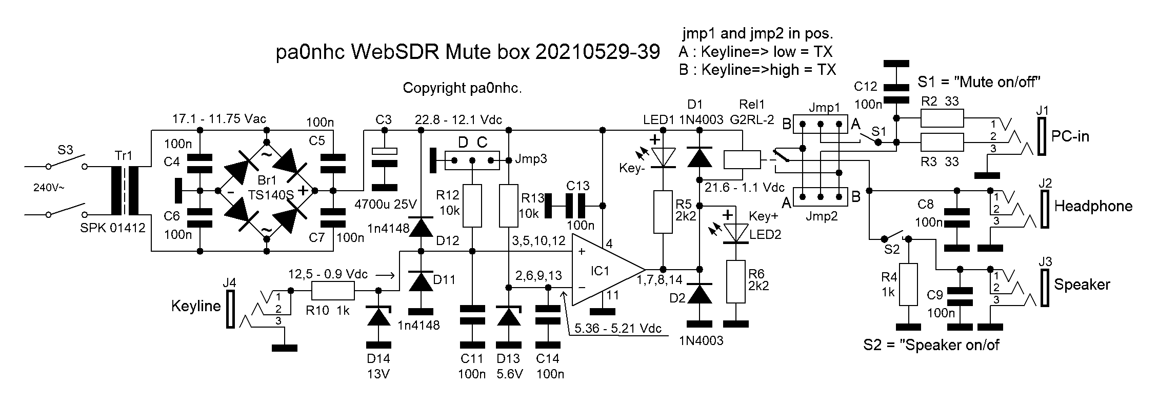
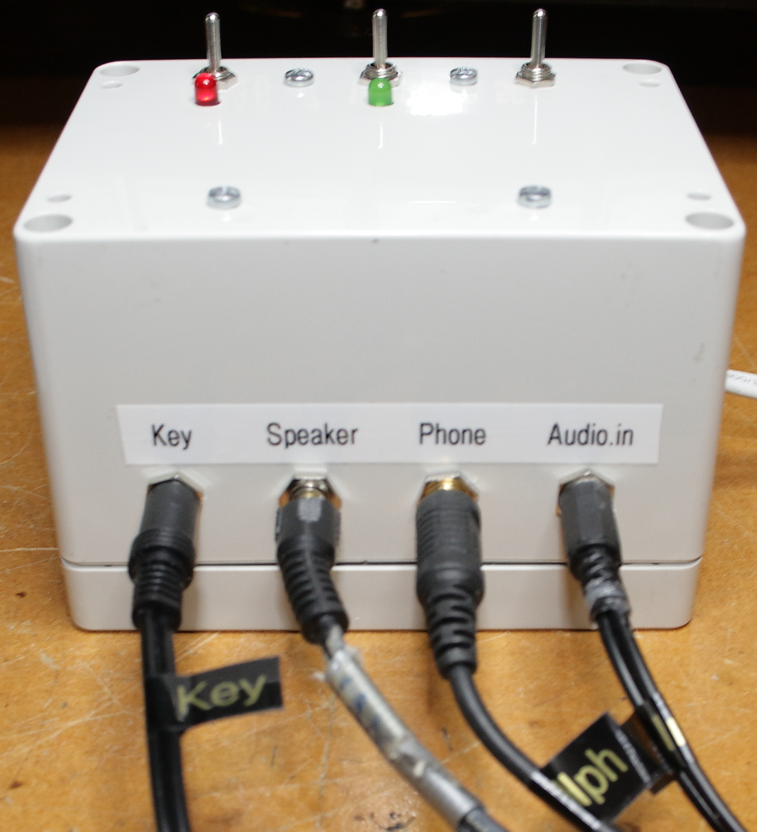
Connections.
Four 3,5mm (or 1/4") stereo busses are used for
connecting two inputs and two outputs. The "ground" connections of all inputs and
outputs are interconnected through the ground planes of the PCB. All connections
are RF-filtered.
An RF filtered and over voltage protected "Key line" bus must be connected to a transmitter "Power Amplifier" relay
output by means of a screened cable .
This transmitter "Power Amplifier" relay output should preferably not
be connected to the cabinet (ground) of the transmitter.
The stereo input L and R lines are individual loaded by 33 Ohm to simulate a
headphone load, ensuring a neutral frequency response.
The headphone and speaker outputs
are mono.
The speaker output is designed to be connected to a high impedance active
speaker or audio amplifier, but is low-impedance-terminated, to prevent hum during muting.
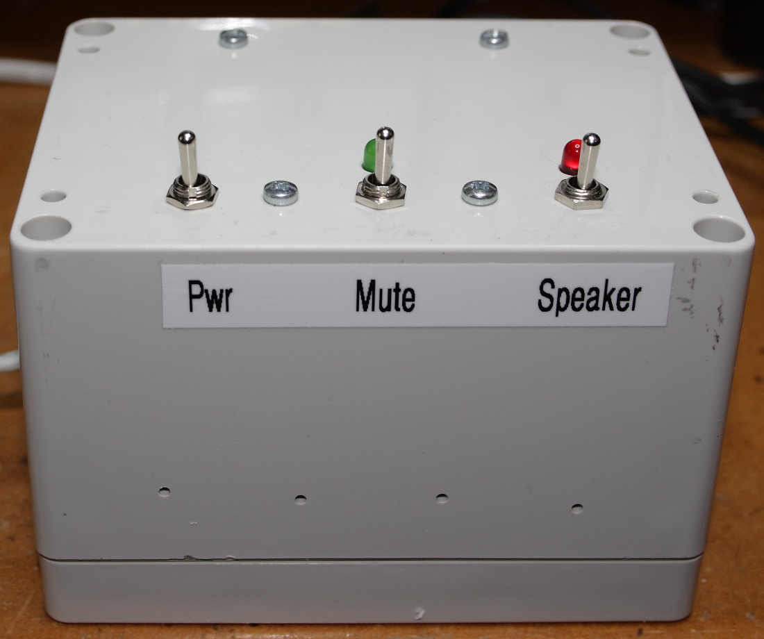
Actions.
Three toggle switches enable :
S1 : continues PC
sound output,
S2 : continues speaker mute.
S3 : Power on/off.
A burning left LED1 indicates "Key line = high"
A burning right LED2 indicates "Key line =
low".
When power is off, no LED is burning.
When
transmitting, the transmitter shortens or opens its "Power Amplifier"
Key line" relay output.
The keyline input switching level is 5.6Vdc for mute or un-mute.
With jumper3 you can set the bias for IC LM324N to "Pull up" or
"Pull down". If in a connected RF power amplifier already has an
active bias, you can leave jumper3 to "Open".
When the "Mute" switch is pushed towards LED1, the SDR-sound
is muted during transmitting.
The
audio will be muted :
When the "Key" line is shorted, and jumper1 and jumper2 are both inserted to position
"A".
When the "Key" line is open, and jumper1 and jumper2 are both inserted to position
"B".
When the "Speaker" switch is pushed towards LED2, the external active speaker is muted. The "Speaker" switch has no influence to the "Phone" output.
Power.
The muter has its own small linear power supply,
which is RF-filtered to be noise free. The little mains transformer is a
special "Short
Circuit Proof" type, making fusing unnecessary.
An external 9-16 Vdc supply could be
used instead. In that case, be aware that all supply "minus"
connections of the muter, the PC, and the
"Speaker" connections will
be interconnected.
Housing.
I advise to use a fully closed and screening metal
box to prevent RF intrusion, for instance Hammond 1590EBK.
I used a Hammond 1554GGY ABS box. The double sided PCB is designed for it. Once finished, is the box resting with its lid on the table surface, and its drilled bottom up. It can be necessary to drill some plastic extensions away at the inside of the bottom of the box.
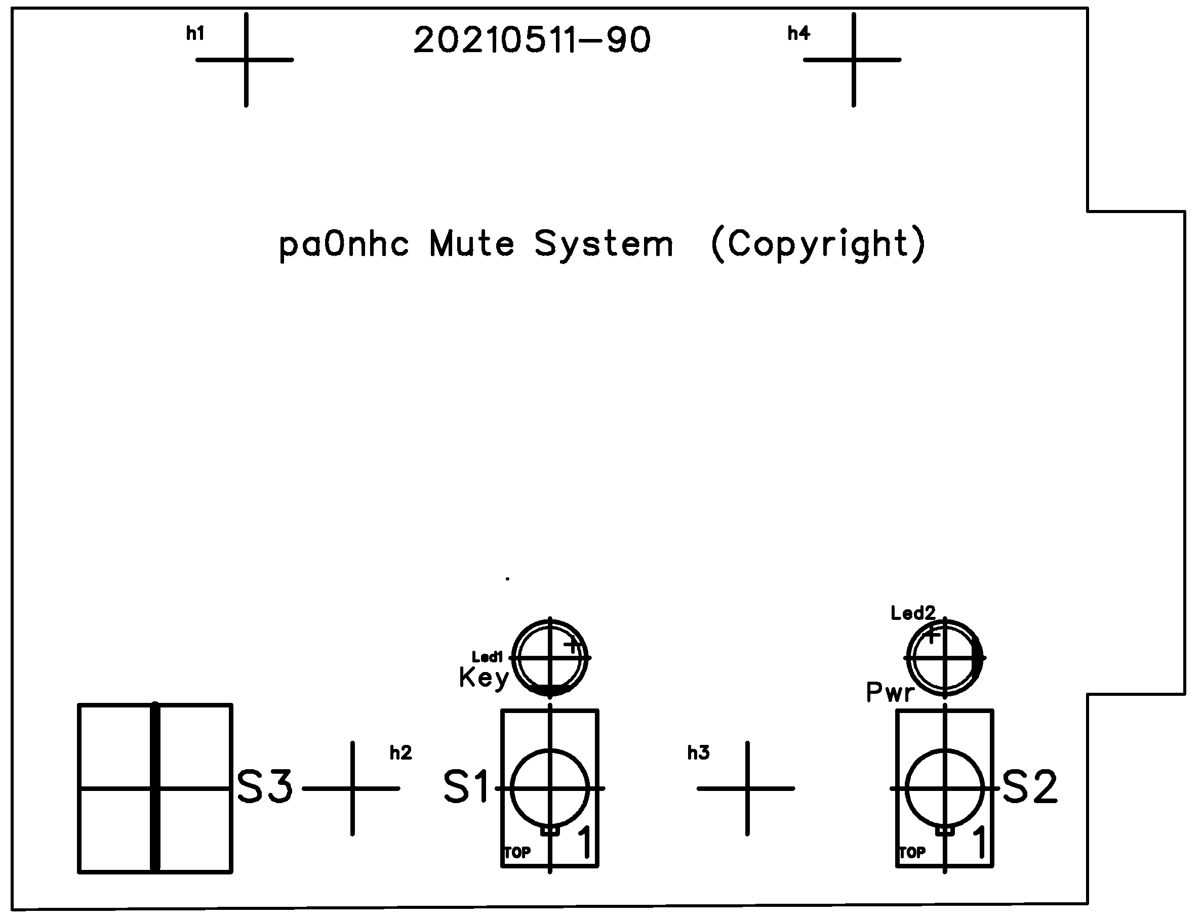
Drilling.
The switches are soldered directly into the PCB. Their relative distances to all
other holes are therefore fixed. Use the empty PCB therefore as a drilling template. If
there is enough internal height in the box, you could connect the switches and
the LEDS to the PCB by wires. Then you are free to place them where you want.
The board has 4 fixing holes, to be used to fix the PCB into the box with (15mm)
distance bushes. Only a few Watts are dissipated, so ventilation holes are
not needed. No holes will be drilled into the box lid.
First drill
all holes at the bottom of
the box for switches, LEDs and fixing screws.
=> If in stead of a double pole mains switch, a single pole mains switch is used, the hole for it in the box
must be shifted by 2.4 mm <=
The LEDs must fit easily into their holes, and should precisely rest with their
rims to the box
internal surface.
Drill the holes for the stereo busses and the mains cable in the back of
the box, further down so they are well free from the PCB.
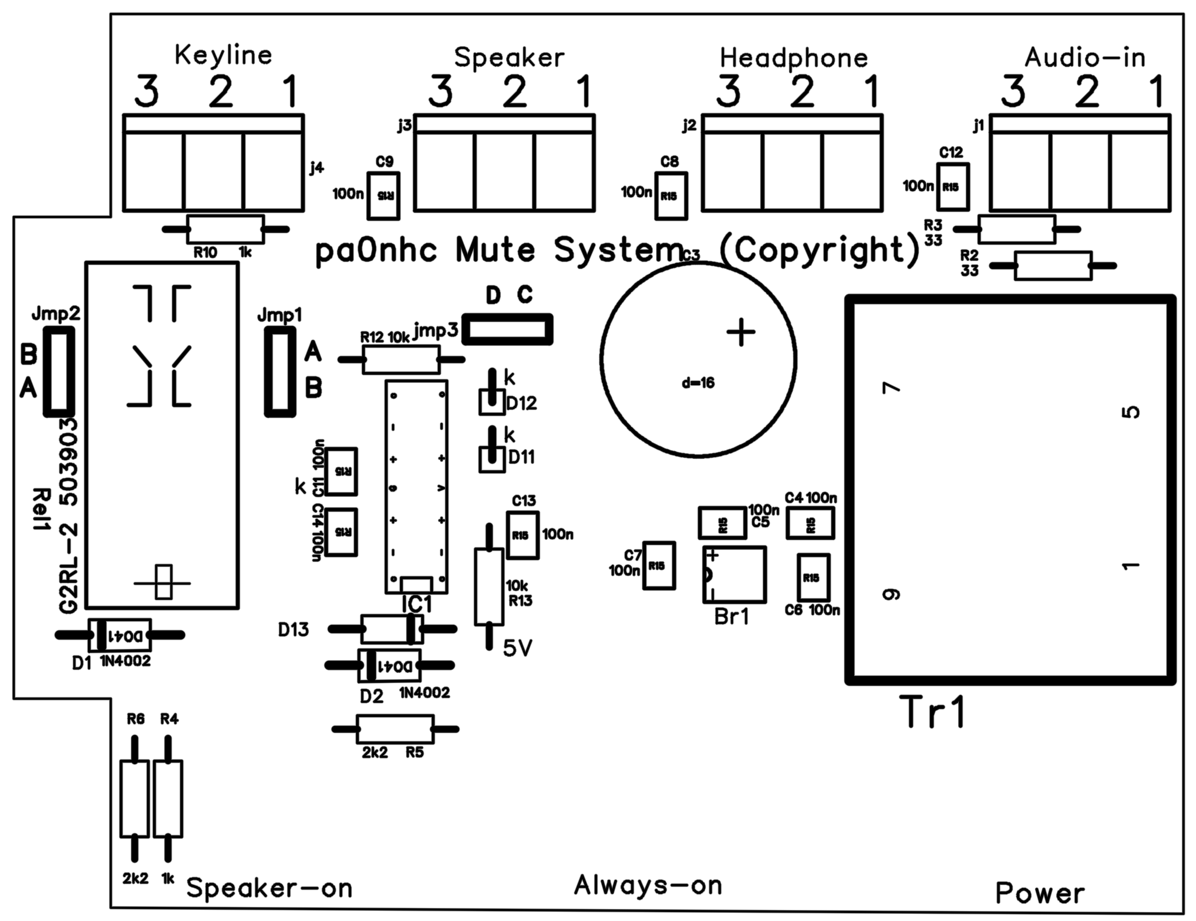
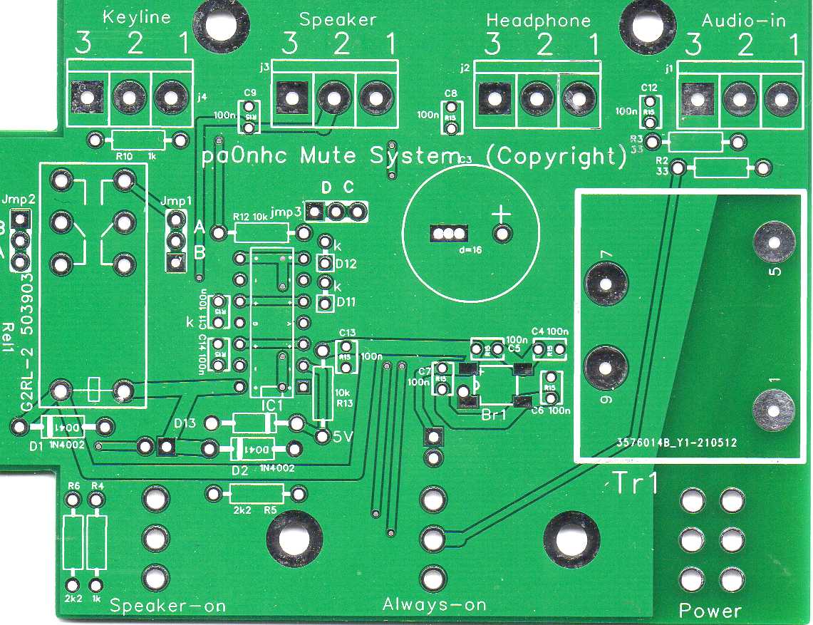
Component placing.
The switches and the LEDs must be placed at the top surface of the PCB.
All other components must be placed at the bottom side of the PCB.
Place and solder one component at a time, and check its
location, position, value and solder quality.
1. First solder BR1 at the PCB bottom side (watch the "+" sign).
2. Go on at the PCB bottom soldering all other low height
components :
Resistors, capacitors, diodes, choke, jumpers, IC socket.
Watch the notch on the socket and the PCB.
Watch the rings on diodes and their "k"
signs on the PCB.
3. Then solder the higher components : screw connectors (if used), the relay,
the transformer and the elco (watch the " +" sign, long wire = +).
4. Mount the four 15mm distance bushes securely with M3 screws into their holes in the ABS box bottom.
5. Place (but do NOT solder) the switches at the PCB TOP in their PCB holes.
It can need some force to press the square pins into the
round holes. Be sure the switches are pressed onto the PCB.
6. Place one nut at each switch shaft.
Adjust the nuts for exactly 15mm space between the PCB
surface and the top
surface of the nuts.
7. Shift the PCB with the switches into their holes in the box.
Be sure that the PCB just rests onto the distance
bushes.
The switches must all be seating with the nuts against the
internal box surface. Readjust the switch nuts if necessary.
Fix the PCB temporarily with M3 screws into the
distance bushes.
This will
align the switches precisely for correct soldering.
8. Solder the switch pins. Use here a higher tip temperature to
prevent cold solder connections. Heath both pins and holes.
Then remove the PCB.
9. Place (but do NOT solder, nor shorten their wires) the LEDs at the PCB TOP. Long wire =
"+".
Watch the flat side at the rim and at the PCB.
10. Mount the PCB into the box.
Carefully shift / press the LED's into their
box holes until their rims are seating flush with the inside of the box.
Solder the LED wires, and shorten them.
11. Solder the mains cord to the power switch.
12. Connect the wires to the input and output busses. See schematic for
correct connections. Screen = pin3.
13. Close the box and stick four soft feet at the corners onto the lid.
Check the correct operation, and change the settings of the jumpers for the actions you need.
Testing.
The "Muter" should pass all PC sound :
- Regardless Muter "Pwr" is switched "Off" or
"On" and
- Muter "Speaker" is switched towards the front.
The "Muter" should block all PC sound to the
"Speaker ::
- Regardless Muter "Pwr" is switched "Off" or
"On" and
- Muter "Speaker" is switched towards the back.
The "Muter" should pass all PC sound to the
speaker :
- Muter "Pwr" is switched "Off",
- Muter "Speaker" is switched towards the front.
The "Muter" should block all PC sound when :
- Muter "Pwr" is switched "On",
- Muter "Mute" is switched towards the back,
- Muter "Speaker" is switched towards the front,
- Transmitter is transmitting.
Jumper settings.
Jmp3-C => Key line pulled to +12V.
Jmp3-D => Key line pulled to 0V.
No jumper => key line is "Floating".
The bias current from the Muter is abt. 1.7 mA, and the max. bias voltage from
the Muter is abt. 17Vdc.
Check the allowed voltage and current values for your radio and power amplifier.
The muter relay switching level is 5.6Vdc key line input.
So keying with a switching transistor which has 1V saturation is no problem.
When the muter is switched off, it should withstand +/- 20Vdc keyline input.
When the transmitter shortens the key line during transmit (like the Hermes
Lite2), put a jumper at Jmp1 "A", Jmp2 "A" and Jmp3
"C".
In for instance a Kenwood TS570D, select the relay output pins at the "Remote"
output
for "Shorted" while transmitting.
If the power amplifier circuitry has also internal biasing, change the power amplifier bias and/or change Jmp3 if necessary.