|
|
|
|
Simple
motor driver for tuning a Magnetic loop antenna. |
(Copyright) The use, copy and modification of all info on this site is only permitted for non-commercial purposes and thereby explicitly mentioning my radio amateur call sign "PA0NHC" as the original writer / designer / photographer /publisher.
(Text
not completed).
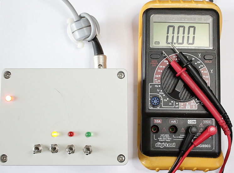
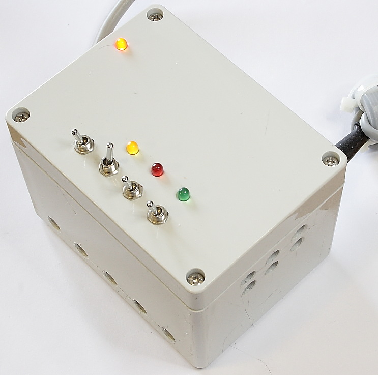
This manually operated little box drives a small 12V
/ 0.5Adc tuning motor.
The used tune motor
must be able to run forwards and backwards, by changing the polarity of its
supply voltages.
When a vacuum capacitor and end stops will be used,
the end switches should change the motor polarity,
and thereby the rotation direction of the motor and tuning capacitor.
|
|
|
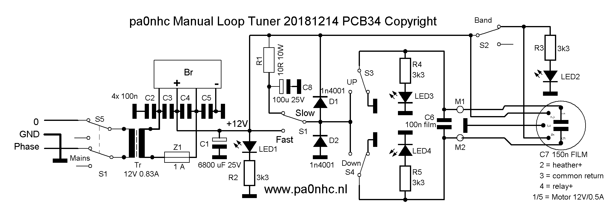
New analog schematic 20181214-34.
This simple circuit is not digital, but linear and therefore does not generate any radio interference. Speed switch S1 is of the ON / NONE / ON type, and sets the tuning motor speed to low or high. At high speed, the motor gets the full supply voltage. Wire wound series resistor R1 reduces motor current for low tuning speed. C8 then supplies a short starting pulse, ensuring positive start of the motor. R1 consists of two 5W resistors in series, to keep component temperatures low. Its resistance value can be adapted for your particular situation.
S5 switches the mains power. The unit should normally be left switched ON, for powering the band switch relay, and an anti condensation heather in the antenna tuning box.
My MFA 3000:1 12Vdc tune motor (Conrad orderNr
222368), plus the 48:10 tooth belt reduction, make in total 14400 : 1 reduction ratio.
The by me used 2x600 pF air
capacitor has no end stops, and can turn fully around in both directions. From max. to min. capacitance
takes 180 degr.
With my 10m circumference loop, tuning from 3.65 MHz to 7.1 MHz needs about. 30
seconds.
 A cheap and small 12V
/ 10VA mains transformer Tr,
a bridge rectifier
Br, and
a buffer capacitor C1 generate 17Vdc (no load) to 12Vdc (full load). The
transformer secondary is fused by 1A slow blow. This is essential to
prevent fire, as a short circuit in the
motor cable will lead to overloading the power transformer.
Anti rattling capacitors C2 to C5 prevent
radio interference, and C6 and C7 will short circuit possible RF energy on the motor
lines. C7 is soldered directly onto the output bus.
A cheap and small 12V
/ 10VA mains transformer Tr,
a bridge rectifier
Br, and
a buffer capacitor C1 generate 17Vdc (no load) to 12Vdc (full load). The
transformer secondary is fused by 1A slow blow. This is essential to
prevent fire, as a short circuit in the
motor cable will lead to overloading the power transformer.
Anti rattling capacitors C2 to C5 prevent
radio interference, and C6 and C7 will short circuit possible RF energy on the motor
lines. C7 is soldered directly onto the output bus.
Suggestion
:
Wind the mains
cable several times through a
Fair-Rite MIX #31 29mm core part Nr. 2631801202, available at
ARROW.COM. Or use a 36mm Ferroxcube MIX 3S4 core, type T36/23/15-3S4,
available at "dx-wire.de" for only 2E40 a piece.
Do the same with the motor cable. This will weaken possible RF currents on both
cables.
These ferrite materials are especially developed for optimal use in common mode chokes, and are relative cheap.
As the transformer warms up a little, even when
the unit is in stand by, i suggest to drill some 8mm ventilation holes into the
cabinet to keep component temperatures low, prolonging their life time ==>>
- six holes at the top of right hand side,
- six holes at the bottom of front side.
Check that no 230Vac contacts
could be toughed.
MOTOR LINES :
S3 and S4 change
the motor rotation direction, by inter changing the polarity of both motor lines.
While one motor line is connected to mass, the other is
connected to the positive drive voltage.
|
Depending on the rotation direction of the motor, each motor line is or grounded, or
contains a positive drive voltage. |
The motor only runs as long as ON / NONE / [ON] toggle switch S3 ("UP") or S4 ("DOWN") is pushed.
|
|
These switches automatically return back to the grounded position. In rest, both motor lines are grounded and short circuited. If the motor is then still running, the motor generates a current in opposite direction, resulting in an immediate stop of the motor, without over shooting its stop position.
With ON / NONE / ON switch S2, an external relay can be activated with +12V at output bus pin4, for instance for antenna band switching.
On output bus pin2 is always +12V present for an anti-condensation heather in the antenna tune box.
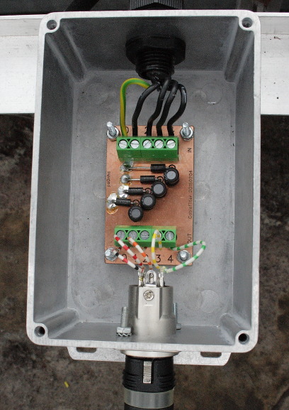
Possible static voltages on the motor lines
should leak to the mains safety ground. The the negative 12V wire in the motor
cable is therefore connected to the mains safety ground
via the PCB mass plane.
In my case, external over voltage protecting diodes
(+ and - 25V threshold) are connected between -12V and all other lines. They
should help limiting spike voltages induced from lightning. The 10 uH chokes
reduce
RF currents. ==>>
REM : In case of a nearby thunderstorm, pull both motor plug and mains plug.