| << |
The similitudes and
differences between the
pa0nhc H-field antenna
and
other active E-field antennas.
pa0nhc
20200711.
20231130.
|
Miniwhip active E-field antennas.
The Hi-Z input circuit of the impedance matcher electronics in a Miniwhip antenna, detects the voltage differences between the antenna surface and
its mass-plane.
These RF voltages will become available at the 50 Ohms coaxial
output.
Why a coax feeder can act as a parasitic antenna.
Between receiver and antenna, signal and noise sources will induce RF currents
on the outer skin layer of the coax screening ("its Common Mode
Circuit").
These "Common
mode noise currents" will travel to the antenna.
They there can enter the
internal coax circuit (its differential
mode circuit).
These noise signals then run through the
inside of the coax backwards
to the receiver.
And will there be heard.
These common mode noise currents will deteriorate the "Signal To Noise
Ratio" of the antenna system .
Less common mode currents will result in improved Signal To Noise Ratio.
 Measures to improve a Miniwhip S/N.
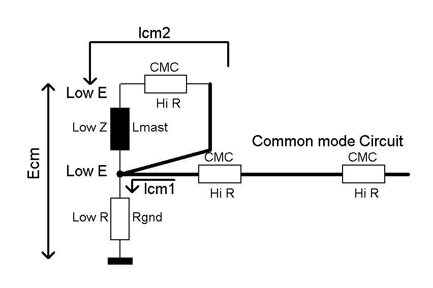
- The bottom of the Miniwhip mast MUST be DIRECTLY, VERY SHORT and
NOISE FREE grounded into the soil.
- The Miniwhip PCB ground surface should be directly connected to the top of
that grounded mast.
- The shielding of the coax feeder should be connected to that grounding
point at the bottom of the mast.
This will bleed common mode noise currents
[Icm1] toward ground, before they can reach the antenna
PCB. This measure is effective for
a wide band width.
- Insert every 3m distance a good common mode choke over the coax.
They will prevent common mode resonaces.
But will be less or not effective at VLF/LW/MW bands.
On VLF/LW/MW and low SW bands, the top of the grounded mast is still low-Z, as the
length of the mast is short compared to the wavelengths.
But on higher SW frequencies,
for instance 29MHz and a (1/4 wave) 2.6 meter long mast, the mast resonates at 29 MHz.
The mast top is then highZ.
Coax common mode currents running through the mast will then cause RF noise
voltages at the top of the mast, possibly worsening the Signal To Noise Ratio on higher
frequencies.
The weaknesses of every active E-field antenna :
- Noise free grounding of the antenna and feeder is absolutely
necessary.
But not always possible, if no free piece of ground (garden) is available.
No ground => poor performance !
-
Screening of the antenna is impossible.
-
Balancing of the antenna is impossible.
- They are VLF/LW/MW and SW DX antennas.
- But they produce
WEAK NVIS signals (sources from distances less than 400
km between 3 MHz and 8 MHz will be 20dB weaker).
My Miniwhip antenna PCB :
Contains a Hi-Z resistive
Common Mode Choke (CMC), inserted between the electronics output, and the
antenna output BNC bus. The CMC impedance is abt, 5 kOhms resistive above 2 MHz.
It will over a wide bandwidth vastly reduce common mode currents running
to the mast, or jumping into the
inside of the coax.
REM
: To prevent a ground loop, the outside of the BNC output bus may NOT be
grounded.
It MUST be left "floating".
Only
the one PCB grounding point must be connected to the top of the mast.
My version of the LZ1AQ
active wideband
receiving loop antenna has better properties than
active wideband E-field antennas.
- Grounding of
my version RXloop antenna unit is NOT needed, nor advised. =>
Simple antenna setup.
- Loop antenna, loop amplifier and splitter are
all fully
shielded.
Common mode noises cannot intrude electronics.
- Loop antenna, loop amplifier and coax feeder are
fully
balanced. Common mode noises will be suppressed.
- The
balanced shielded loop caries at both terminals
equaly strong and in phase
common mode noise currents.
- The balanced input of the loop amplifier will suppress these common mode noises by
at least 30 dB.
- The output of the antenna amplifier is also balanced,
transformer coupled,
including a CMC in its output.
- Due to the fully balanced and fully
screened construction, my loop antenna common mode suppression remains very good
down to 15 kHz VLF.
- This is a vertically standing loop, beside low incident (DX) signals, it also
receives NVIS
omni directional.
- By turning the loop around its vertical axis, it can suppress low
incident signals by more than 30 dB (! very sharp) .
- CMCs every 3m over the coax prevent 1/2 lambda resonance and
amplified noise regions.
-
Common mode noises are vastly suppressed.
- Compared with some active loop antenna webSDR stations, resulting also
in far weaker thunder storm lightning noises.
| The balancing and screening measures proved to be the most
effective for S/N improvement. |
The common mode suppression in my RXloop is so high, that it can only be concluded observing very
strong, over -50 dBm, signals or noises.
When the power to the
antenna is switched off, less strong signals will vanish below
the receiver noise floor (equivalent to -120 dBm).
Why so much CMCs over the feeder ? Overkill ?
In his
articles K9YC suggests :
- Asymmetrical antenna systems and 1/2 wavelength long feeders cause high voltages on the antenna and
transmitter.
- Use a symmetrical antenna, and install a good CMC at its feed point.
- Install a CMC at the transmitter (or matcher).
- Install a CMC halfway the feeder.
I
concluded : this is also valid while receiving.
|
I discovered that
feeder 1/2 lambda
common mode resonance's can cause amplified noise levels, around
frequencies where the feeder length is a 1/2 lambda, or a multiple of a
1/2 lambda.
This phenomena can be cured by installing good CMCs at distances of
maximal 1/4 lambda for the highest antenna frequency band.
For instance : a 21 meter long feeder can cause amplified
"noise hills in your waterfall display" around 3.6 MHz, 7.15 MHz, 10.7 MHz, 14.3 MHz
etc.
Using a 3.65 MHz mono band antenna, beginning at the antenna feed point, and ending at the
transceiver, install CMCs at distances less
than 20m.
Every CMC : Wind 14 turns RG400 coax through one 61mm diameter mix #31 core : FairRite
2631803802.
For a 15 kHz - 30 MHz wideband active receiving antenna, install
wideband CMCs at distances of about 3 meter.
Every CMC : Wind maximal turns thin RG316 coax through a split 39 x 19 x 48 mm
"SnapIt" core : FairRite 0431176451.
Be sure the coax turns fit
a little loosely inside the core hole.
The core
halves MUST easily close without an air gap. |
How to diagnose common mode resonance effects :
Do you suspect this phenomena, than you can test it by temporarily inserting an
extra piece of feeder coax.
If the suspected noise "hills"
shift down
in frequency, they are caused by a Common Mode 1/2 lambda resonance.
Valid for all active wideband receiving antennas :
Install CMCs over the feeder coax at distances of ~1/4 lambda
for
the highest frequency used.
For instance :
- Highest frequency : 30 MHz,
- Wavelength : 10 meters.
- Multiple CMCs inserted on the feeder at distances of about 3m .
REM : Start with CMCs at the receiver, and the active antenna unit.
Fill the feeder with CMCs in-between.
The
result will be, that no common mode resonance's, nor amplified noise hills in
the waterfall screen can occur
below 50 MHz.