|
|
|
|
|
|
Pa0nhc small
magnetic
active NVIS receiving antenna. |
Properties :
- Unsusceptible antenna unit.
- Much smaller size than a dipole antenna or loop antenna.
- Antenna directive pattern is like a full size dipole.
Excellent NVIS antenna for 160m, 80m
and 40m..
Good for groundwave reception between
10 kHz and 1.6 MHz.
If rotate able, low
incidence noise
sources can vastly be weakened.
- Very selective. Acts like a very good pre selector.
- Good sensitivity due to the use of a for the used frequency bands Hi-Q ferrite
ferrite rod and Hi-Z FET input.
- IMD-free, the specially designed electronics can handle very
strong signals.
- The input circuitry is guarded against very strong field strengths like a
local transmitter and nearby lightning.
- Remotely tunable with :
Super simple (one coax)
connection between tuner unit and antenna unit ( developed by pa0nhc).
- The prototype tunes between 3,5MHz and 3,8MHz.
Adaptable for other frequency bands.
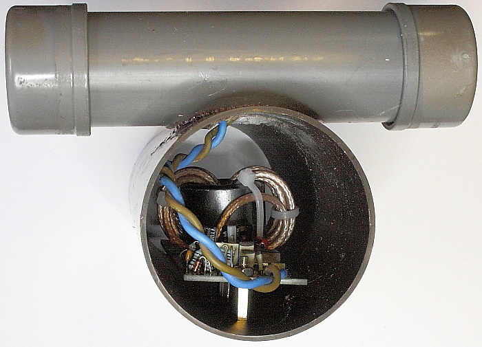
- The antenna ferrite rod fits inside a piece of 32mm PVC pipe.
- The antenna PCB fits in a piece of 50mm (ALU or PVC) pipe.
- The antenna PCB contains a coax mantle current choke (** see optimal ferrite
materials **)
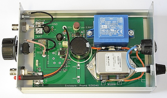
- Build-in noiseless power supply with optimal mains noise filter.
- The tuner PCB fits inside a neath and cheap Proma
ALU enclosure.
- The PDF parts list gives suggestions for perfect fitting components, with ordering data
for "www.conrad.nl", and details for other suppliers.
|
|
|
|
|
|
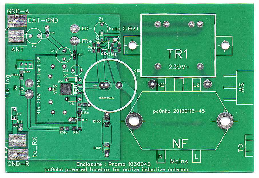
Military grade PCBs : "Order PCB set"
- Double sided
with on both sides mass planes for clean signals.
- With wide top and bottom inter connecting vias.
-
No cooling profiles needed. All SMD semiconductors are contact cooled by soldering hem directly onto the PCB plane.
- All parts soldered on top plane
- Enlarged SMD solder pads for easier soldering.
- Optimal combination of through-hole and SMD components
- Green top and bottom solder masks => NO undetected short circuits.
- White top silk with clear component outlines and texts for easy assemblage.
To prevent
unauthorized commercial
exploitation
by others, schematics below do not contain component IDs nor
values. BUT :
- both PCBs contain top silks with all component IDs.
Correct placing of components should be easy.
 |
 |
 |
REM :
The given component data below
ensure that the performance is as designed, and that components will fit onto the PCB.
If you want to order components from another supplier, use the component
details :
1. mentioned in the ordering data below,
2. given from the
Conrad site.
At Conrad :
- above order amount of 35 Euro postage is free.
- their own brand TRU COMPONENTS often are cheapest.
|
|
|
|
|
|
|
|
|
|
|
|
|
|
|
|
|
|
|
|
|
|
|
|
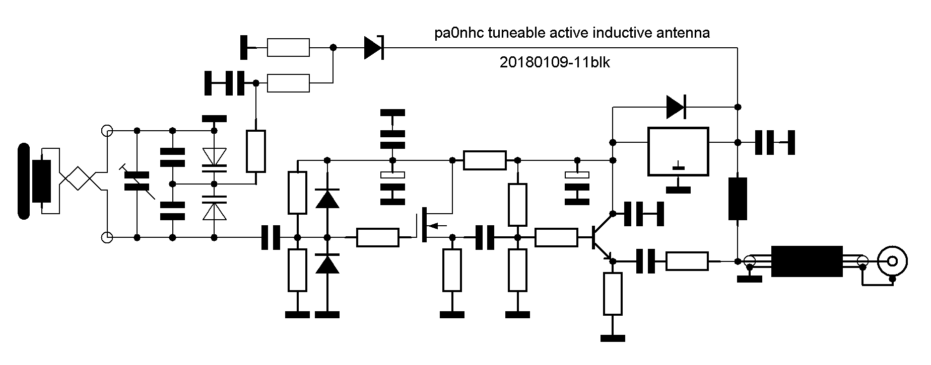
Some design details.
Antenna
unit.
The sensitivity and selectivity are maximal due to the use
of an optimal type ferrite rod.
REM: a test with balanced
and a screened coils gave much weaker signals.
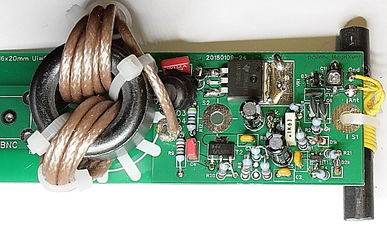
Superb large signal properties are obtained by "Back-to-back"
connected capacitance tuning diodes, an optimally setup source follower buffer/driver with a very steep
single gate MOSfet, and the emitter follower output using a very high-Ft UHF
transistor.
The input circuitry is guarded against damages by fast switching diodes.
An on-board broad band common mode choke blocks noises coming from the coax mantle.
|
The antenna unit PCB (not at the
BNC-bus) should be grounded directly onto a
noise free grounded mast. |
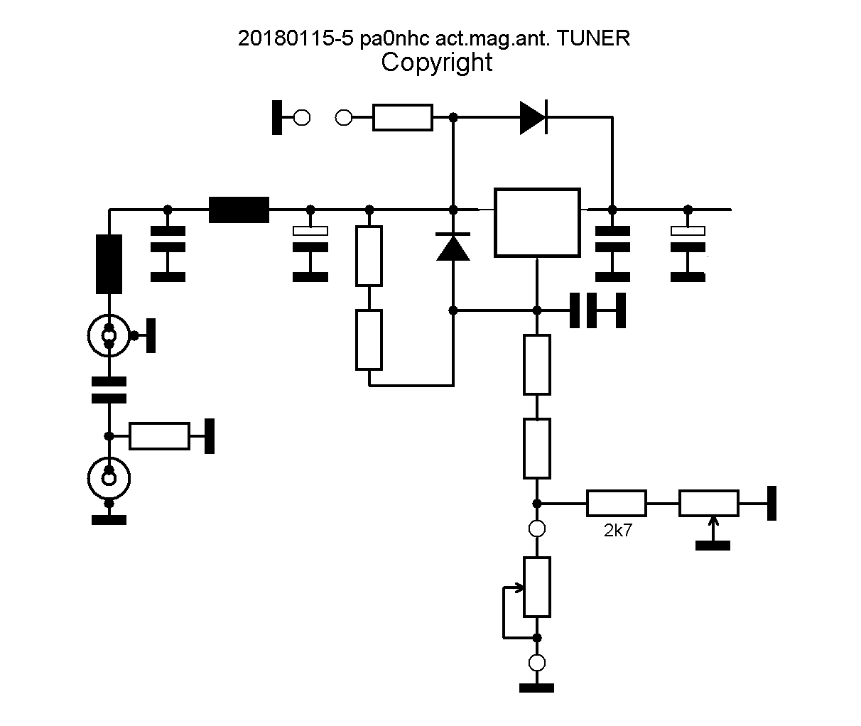
The
tuner unit has a build-in noiseless power
supply with mains noise filter.
To prevent injection of noises from mains power lines, the tuner PCB is
designed for maximal RF-isolation between the mains and the DC-output :
- All mains-related components are on the back of the unit.
- All other components are at the front side.
- The whole unit is NOT connected to the mains safety ground.
- The "ground" connection at the output side of the optimal type mains
noise filter, is connected to the (grounded) housing of the tuner unit,
not to the with noises polluted mains safety ground.
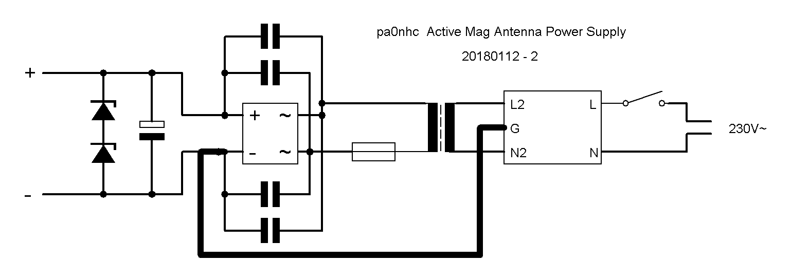
- The little mains transformer has very small parasitic coupling capacitances,
due to separated chambers for primary and secondary windings.
- The bridge rectifier is a low drop type, with all diodes bypassed with capacitors to prevent rattle
and IMD.
- Both PCB sides contain screening ground surfaces.
Grounding
and safety (your own responsibility !) :
Your mains power group should contain
an automatic ground leak current detecting safety switch.
|
IF the antenna PCB is grounded to a noise free grounded mast :
IF your antenna PCB is not
grounded : |
Connecting mains power.
As the tuning unit contains a good mains noise filter,
including filter capacitors, a little ground leak current will flow.
To protect static sensitive equipment, and avoid an unpleasant feeling when (dis-)connecting
cables, i advise you to plug the 240Vac mains cable only into a wall
socket, when all other cables are connected.