 5. Cut, saw, file and press all plungers in shape (see drawing).
Assembling all plungers, central conductors, topplates and links. mod: 000118
5. Cut, saw, file and press all plungers in shape (see drawing).
6. Solder all tuning-rods in the topside of the plungers using a torch.
7. Clean the inside of the central conductors and the outside of the plungers.
Insert the plungers into the central conductors and check the fitting of the plungers in
the central conductors. You MUST have to use some force when moving the plunger.
8. Place the assembled central conductor on two wooden calipers. Carefully warm up the central conductor with a torch and tin it on the spot where it must be soldered to topplate "A". Keep the tinned area small.
9. Shift the caliper near the top to the position, that the side of the caliper is near the top of the central conductor, on about the correct position for topplate "A".
Slip the topplate over the pipe and let it rest to one side of the wooden caliper. It should now nearly be in the correct position to be soldered.
Use small clamps to fix the topplate to the side of the caliper.
Shift the central conductor to get the topplate exactly on the right spot.
If nessacery, use a little blowtorch, to warm up the pipe (NOT the copperclad), just under the melting-point of the solder.
Solder
both sides of the topplate to the pipe. Since the pipe is
still hot, this easely can be done.
On the topplates, all soldering must be clean and smooth! Do NOT use to much solder (electrical losses). Clean the soldered places.
First finish all central conductors like this.
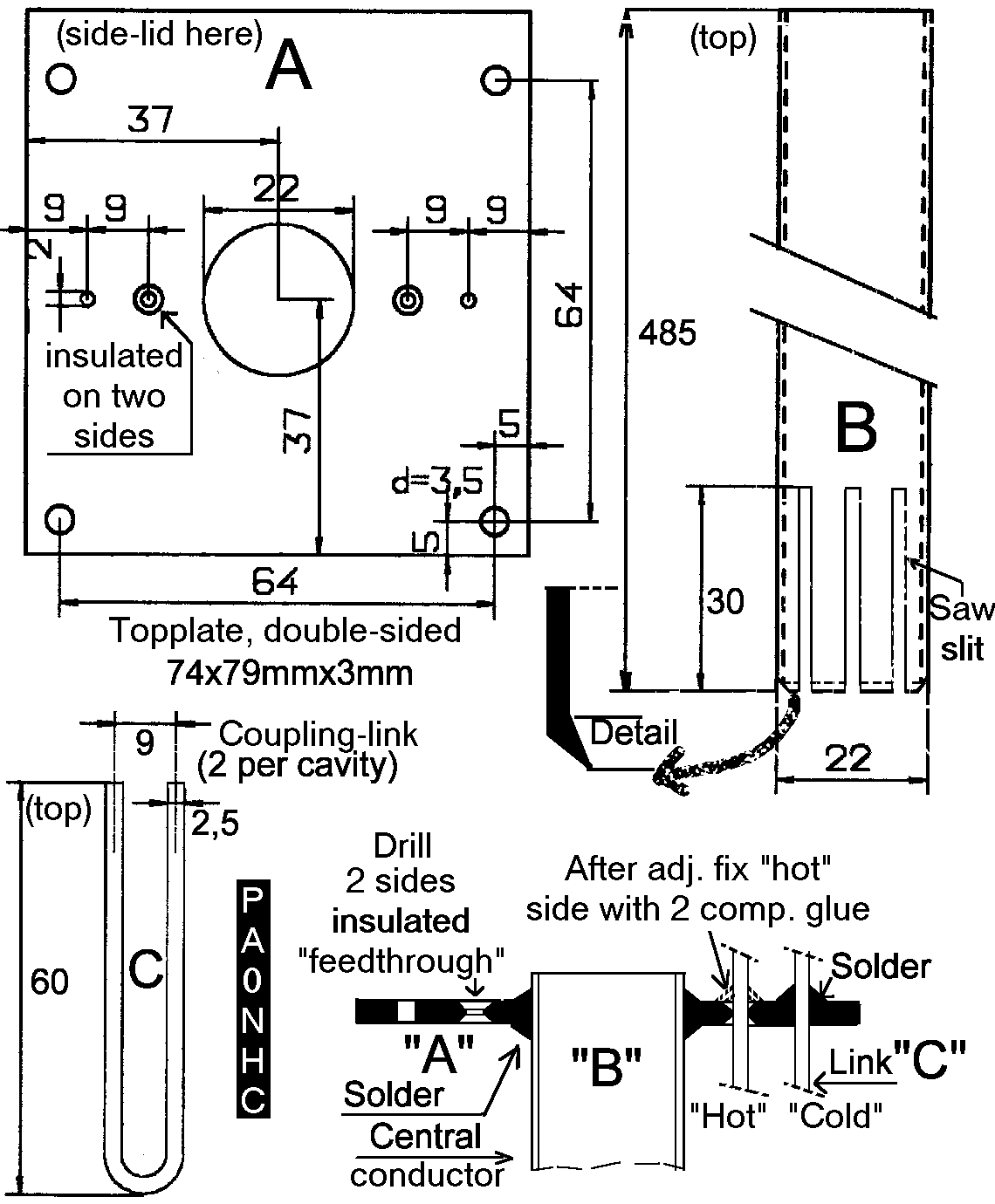
10. Fabricate all the coupling-links "C" from 2.5mm silvered (tinned) copperwire (see "top.gif").
MARK each coupling link, with a waterproof marking-pen, at a distance of exactly 40mm from the lower
(closed) end. During adjustment you can see then, how deep the coupling-link "C" is in the
cavity.
11. Solder all the coupling links temporarely in topplates "A" so, that the
links are 30mm in the cavity.
The pen-marking on the link is then abt. 7mm above the topplate (topplate
thicknes 3mm). Solder ONLY to the topside of plate "A". Leave the
links at the inside of topplate UNsolderd.
The links must run in parallel to the central conductor.
Use little solder at this moment. Later, during adjustment, the links must be
desoldered, moved up- or downwards a little, and resoldered.
Remark:
when the cavity is closed, and the links must be repositioned, you cannot
resolder on the inside.
After final adjustment of the cavity, the links will be fixed to topplate
"A" with 2 component glue at the "hot" side of the link.
After that the mass side wil be soldered firmly to the top side of plate
"A". Thereafter the links never need readjustment.