17.3 Adjusting the shift in a single C-notch-cavity.
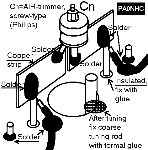
17.3.1 Solder the 1/2 wave testcables at the in- and output links. Do this directly at the mid-point of the strips, at the LINK-side (not at the stripside!), directly on the link-wire (See "cn.gif").
17.3.2 The cavity must be pre-tuned to abt. the pass-frequency.
Measure the frequency-difference between the minimum output at the notch-frequency, and the minimal VSWR at the pass-frequency (NOT minimal insertionloss !).
This is called the "shift". It must be exactly -600 kHz.
17.3.3 Adjust the trimmer C and check the shift repeatedly.
Increasing the value of C will make the "shift" smaller, but the notch less deeper.
17.3.4 It is possible, that the pass-frequency is moved a little, when the notch-frequency is adjusted. This is called "pulling".
Therefore, allways measure BOTH pass-frequency (min. VSWR) and notch-frequency (min output) to obtian the shift.
After the shift is correctly adjusted, NEVER adjust Cn again! Lock Cn.
The notch deepness of each individual cavity should be 30 to 35 dB.
17.3.5 After adjusting the shift:
With the signal generator on the repeater Tx (downlink) frequency, tune the cavity exactly as possible for lowest VSWR (tune with the tuning-rod).
Keep the fine-tuning bolt near the "3 turns in"-position to allow easy fine-tuning later.
17.3.6 Check again for correct shift.
17.3.7 Remove the testcables.
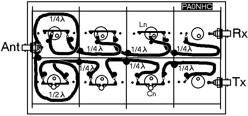
17.4 Drill (two) 3mm holes where the coaxes must pass the sidewalls of the cavity (See "topvuw.gif").
17.4.1 Connect the definitive 1/4 wave PTFE cables at exactly the same points where the testcables were connected.
17.4.2 Solder the braid directly to mass. Do not use braid-pigtails! Try to avoid crossing of input- and output cables. See drawing.
17.4.3 Solder the braid on several points to the topplate "A", and on both sides to the holes in the sidewalls. This prevents unwanted coupling-currents on the outside of the coax, and mechanically stabilises the position of the cables. See the thick dots in the drawing.
17.5 The out-going link of the last C-notch-cavity must be connected to the antenna-recepticle through a >>> electrical 1/2 wave <<< cable.
The length of this cable is critical. It influences the overall notchdeepness of the duplexfilter.
Keep the unsheelded cableparts as short as possible!
Measure the total (straight) length of the inner insulation.
Calculate this mechanical length from the wavelength (at the notch-frequency) and veloctyfactor of the PTFE cable.
17.5.1 Solder the braid on several points to the topplate "A", and on both sides of the hole in the baseplate "H". See the thick dots in the drawing.
17.5.2 Solder at the antenna-side the end of the cablebraid directly, and as short as possible, to the outside of the connector. Do not use a pigtail.
17.5.3 Solder the inner conductor of the cable as short as possible to the central pin of the connector.
Best use N-type recepticles. They are more relyable then BNC!
17.5.4 The 1/4 wave cable, coming from the last cavity of the L-notch part of the filter, will later be connected here in the same way.