Adding a notch-L to a cavity (shift: +600kHz, uplink).
Warning: At a L-notch-cavity the positioning of the cable connections on the links, is even more critical with respect to the "shift", then at the C-notch cavities!
18.1 Shorten the "mass"-side of the links completely down to the topplate "A".
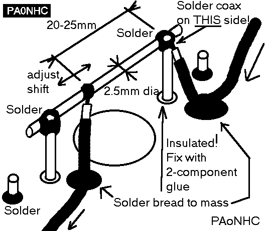 18.1.1 Solder the notch-L to the "hot" side of the links, a few millimeters above the upper end of the central
conductor pipe.
18.1.1 Solder the notch-L to the "hot" side of the links, a few millimeters above the upper end of the central
conductor pipe.
Use (silvered) wire of 2.5mm dia for the notch-L.
18.1.1.1 Shorten the ends of Ln close to the link.
18.1.1.2 Shorten the end of the links close to Ln.
18.1.2 Connect a prefabricated 1/4 wave (notch-frequency) 50 ohms high quality PTFE
cable,
centre conductor on the out-going side of the cavity to Ln,
and the screening to the mass surface of the topplate (not to the link), like shown in "ln.gif".
This is the shortest way to connect the cable to mass.
18.1.2.1 For the adjustment-procedure only, this cable must temporarely be lenghtened with an extra 1/4 wavelength 50 ohms coax with plug, to be able to connect it to the measuring-instruments.
18.1.3 Solder on the input-link a 1/2 wave 50 ohms test-cable. Use a short mass-connection. Solder the inner conductor
exactly on the crosspoint of the link and Ln, to the LINK, not to Ln (see "ln.gif"). Do use little solder.
18.1.3.1 This way, you lateron can solder the definitive PTFE cable (which is coming from the cavity on the "Rx"-side), to exactly the same spot.
This is very important, in order to keep the then allready adjusted shift unchanged, when connecting the cavities together. Pay attention to this point! Even the size of the solderpoints here can have markeble influence on the shift.