 18.2.4 Adjustment is very critical. Even the size of the solderpoints is of influence!
Adjust and check repeatedly.
At this time only look to the frequency-difference between notch and min. VSWR (= shift).
18.2 Adjusting the shift in a single L-notch-cavity.
18.2.1 Pre-adjust the passfrequency within 10 kHz from the wanted frequency.
18.2.2 Measure the frequency-distance (shift) between the minimum output at the notch-frequency, and the minimal =VSWR= at the pass-frequency (NOT the maximum output).
18.2.3 Moving the tap on Ln will change the shift.
18.2.4 Adjustment is very critical. Even the size of the solderpoints is of influence!
Adjust and check repeatedly.
At this time only look to the frequency-difference between notch
and min. VSWR (= shift).
After the shift is correctly adjusted, NEVER adjust the tap on Ln again!
18.2.5 Tune the cavity exact as possible for lowest VSWR to the pass-frequency.
Tune with the course tuning-rod, and keep the fine-tuning bolt abt. 3 turns in, to allow easy fine-tuning later.
18.2.6 Check again for the correct shift.
18.2.7 Remove both testcables, but leave the PTFE cable connected to Ln on its place (it must not be shifted or resoldered).
The free end of the PTFEcable will be connected later to the input of the next cavity or the antenna connector.
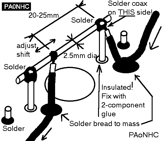
18.3 Drill, where the coax must pass the sidewall of the cavity, a 3mm hole close to topplate "A".
18.3.1 Connect the 1/4 wave PTFE cable coming from the former cavity (on the Rx-side of the filter), to exactly the same point onto the input-link, where the testcable was connected. Use little solder.
This ensures that the shift of this cavity is the same as adjusted.
18.3.2 Solder the braid directly to mass. Do not use braid-pigtails! Try to avoid the crossing of input- and output cables. See drawings.
18.3.3 Solder the braid on several points to the topplate "A", and on both sides of the holes to the sidewalls. See the thick dots in the drawing.
18.3.4 The PTFE outputcable, wich still is connected to Ln, will later be connected to the next cavity (or at the antenna connector).
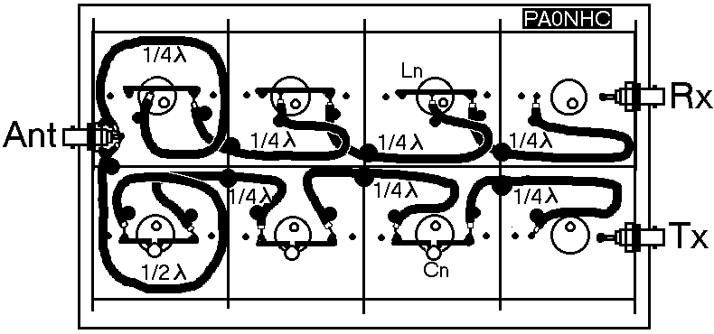
18.4 At the LAST L-notch-cavity, the out-going 1/4 wave PTFE-cable cable, wich is connected to Ln, must be connected to the antenna-connector.
PS: It is VERY important that as this point the electrical length of the 1/4 wave cable is exactly 1/4 wavelength! This influences the overall notchdeepnes of the filter! Remember: PTFE has a different shortening factor than normal cable! Measure the length of the inner PTFE-insulation.
18.4.1 Solder the braid on several points to the topplate "A".
18.4.2 Solder at the antenna-side the cablebraid directly, and short as possible, to the outside of the connector. See drawing.
PS: In stead of BNC better use N-type of recepticle on the duplexfilter. It is mechanically and electrically better (less chance of contac tproblems).
18.4.3 Solder the inner conductor of the cable AS SHORT AS POSSIBLE, directly to the central pin of the connector. See drawing. Keep the unscreened length of the cable-inner as short as possible. This can influence VSWR. If at hand, use a special conical nut instead.
18.4.4 The 1 / 2 wave cable, coming from the last cavity of the C-notch part of the filter, is here connected at the same way. See drawing.
PS: It is VERY important that as this point the electrical length of the 1/2 wave cable is exactly 1/2 electrical wavelength! This influences the overall notchdeepnes of the filter! Measure the length of the inner PTFE-insulation.