|
Electronics for a top quality DIY condenser microphone. |
Download and save pictures by right-clicking on "PDF".
Print the B/W masks in/as : color, photo, max. saturation, max contrast, 100% or original size..
Purpose of this design.
A top quality DIY condenser microphone for 48V phanton power.
The microphone cartridge can be :
1. A "real" condenser needing 25V bias
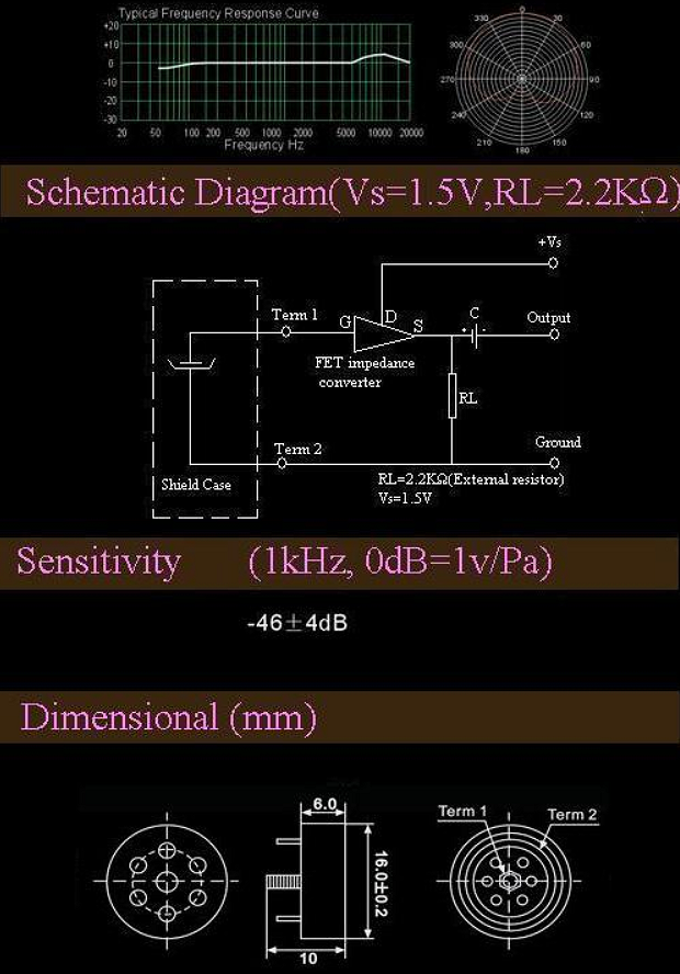
2. A high quality electrets cartridge needing no bias ( ! NO fet inside ! ). See info below.
3. A standard electrets cartridge which has a build in FET, then read Unidirectional floor microphone .
Properties (2kOhm load, 48V power):
Class A design :
High max. output +12dBu !
Very low 2nd harmonic distortion: better than -60dB @ 1kHz/0dBv !
Optimized FET input:
Lowest possible noise level
Largest possible dynamic range (typ. 118 dB).
Gain 0,9x (-1dB).
25V bias available
without noisy bias oscillator
DC coupled opamp line driver :
optimal canceling of hum and noises induced on the balanced microphone cable ( typ. 50dB of better !)
Response 8Hz-43kHz +0/-3dB
No damage when connecting/disconnecting/reversing supply voltage
Short switch-on-time (< 10s)
Output impedance 200 Ohm, 8Hz - 43 kHz (can be adapted to your wishes).
Which microphone cartridge is suitable ?
High quality electret's cartridges WITHOUT BUILD-IN FET can be recognized from the threaded bolt protruding on the back side. This is the cartridges signal output. They are
produced by "Lingbo Longxing Electronic Company Ltd" lxmic.com
. They have a wide and flat response. You can find such a cartridge in Behringer C2 microphones.
Uni-ECM-LX16162W (like used in Behringer C2).
Test circuit with external FET.
PDF
Large membrane condenser capsules, up to 32mm dia and multi-pattern, sometimes can be found on eBay of Alibaba.
Special components:
R1 en R2 are 6,5x2,5mm axial 1 GIGAohm (= 1000 MEGohm !) resistors. Obtainable at Digi-Key .
"Ins1" and "ins2" are ceramic insulators pressed in the PCB. On them R1, C1, R2 and T1 have to be soldered, free from the PCB
surface.
Low noise 2SK170 FETs are obtainable at eBay .
NB: use the cheapest available, matched pairs ar not needed. Buy some more so you have a choice.
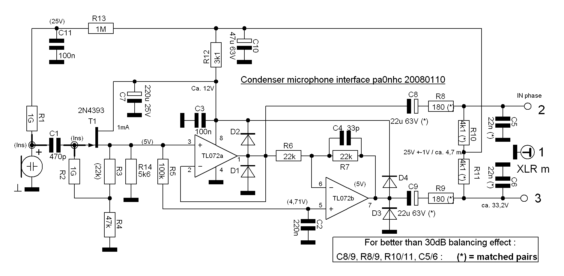
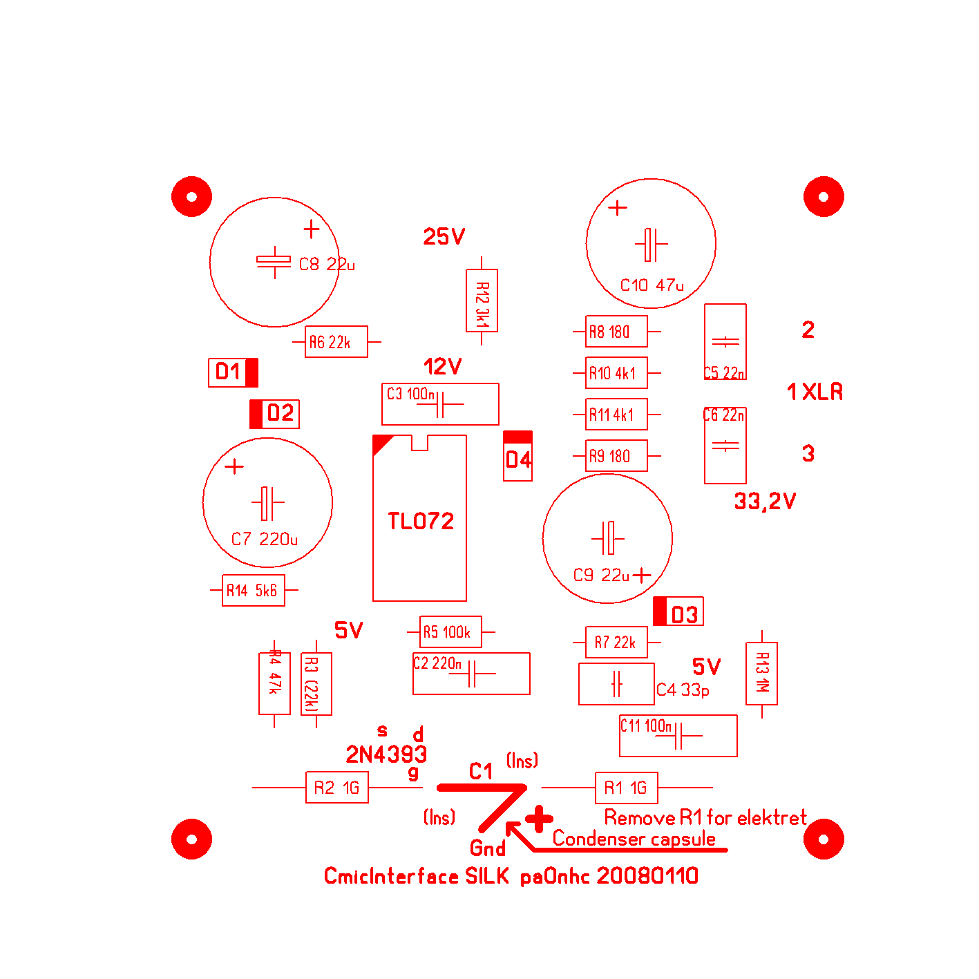
The schematic diagram.
When an elektret microphone cartridge is used, R1, R13 en C11 are omitted.
PDF
Two PCB designs are available:
1. A double sided narrow PCB only 75,8x17,7mm. It fits inside a 22mm tube for making a "Pencil" type microphone.
2. A square PCB 42x42mm, DOUBLE or SINGLE sided. Fits inside a small box. Usable for making a boundary microphone.
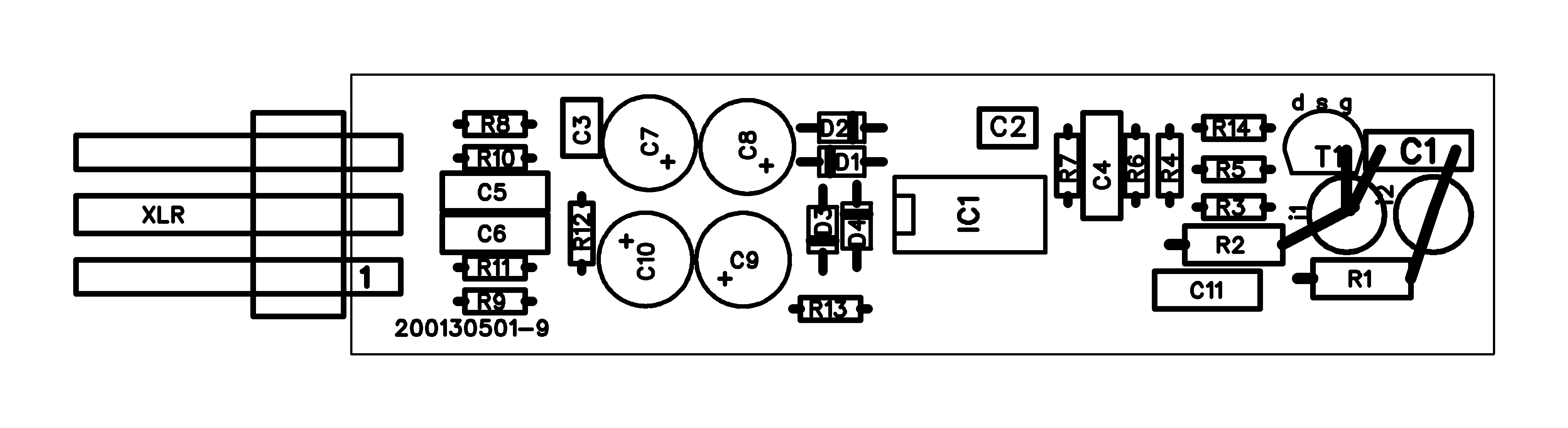
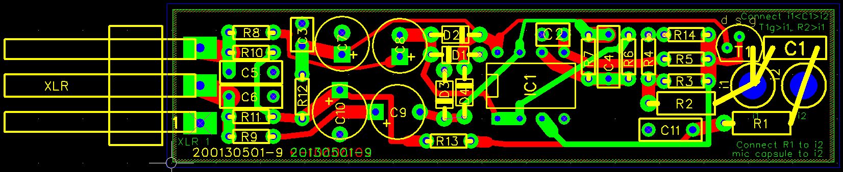
PCB No1.
This PCB is designed using FREEPCB,
FREEWARE, including libraries and auto router.
Recommended!
|
|
|
C3 and C4 should be a few mm above the PCB in order to be able to solder their connections on BOTH sides of the PCB. |
|
|
|
|
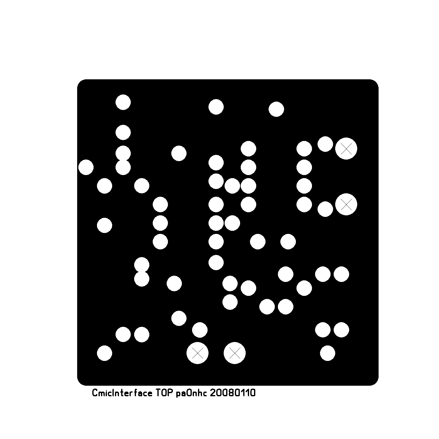
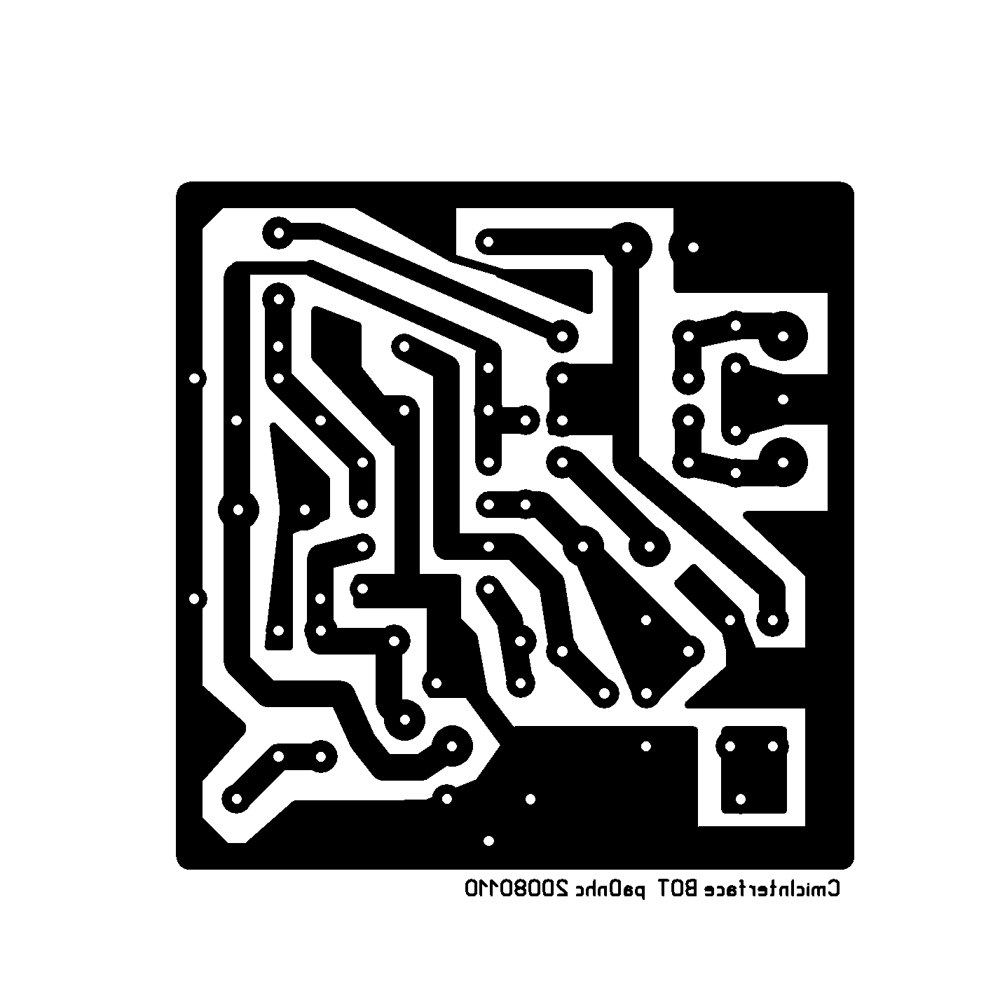
PCB No2.
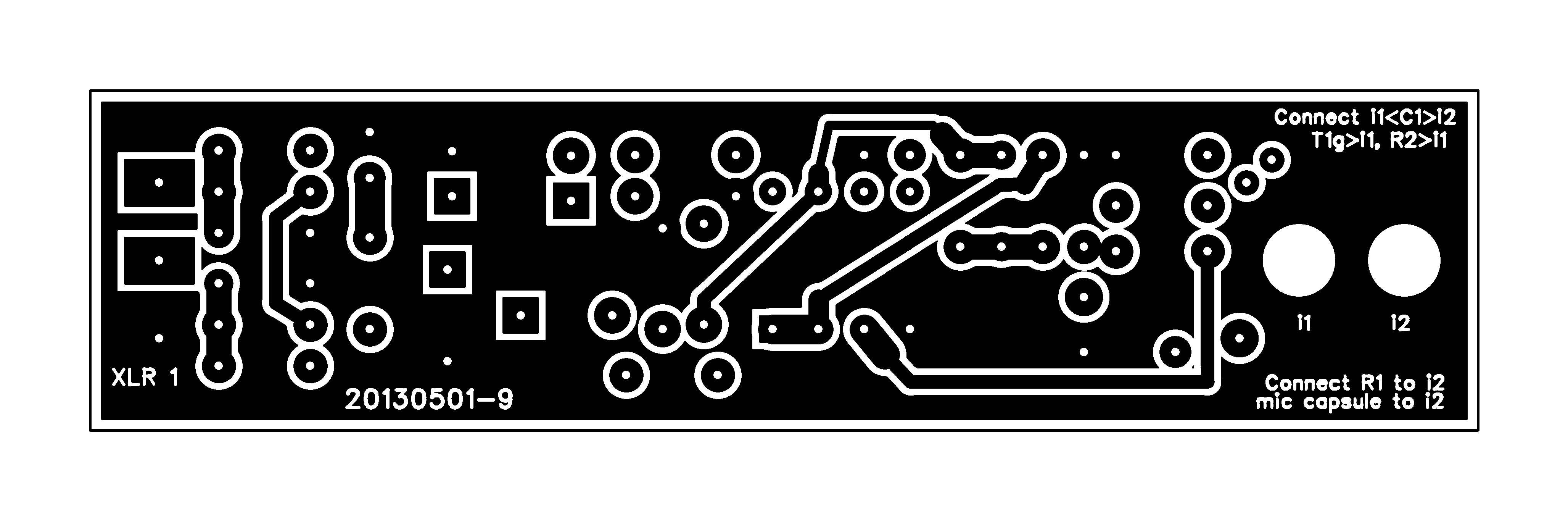
Both masks are shown like they will be seen on the PCB surfaces. Resolution = 600DPI. Dimensions ca. 42mm x 42mm. Wherever possible connections should be soldered on BOTH sides of the PCB.
Used double sided:
On the top-copper side, some holes are intentionally NOT insulated. They serve as "vias".
You MUST solder these connections on both sides of the PCB.
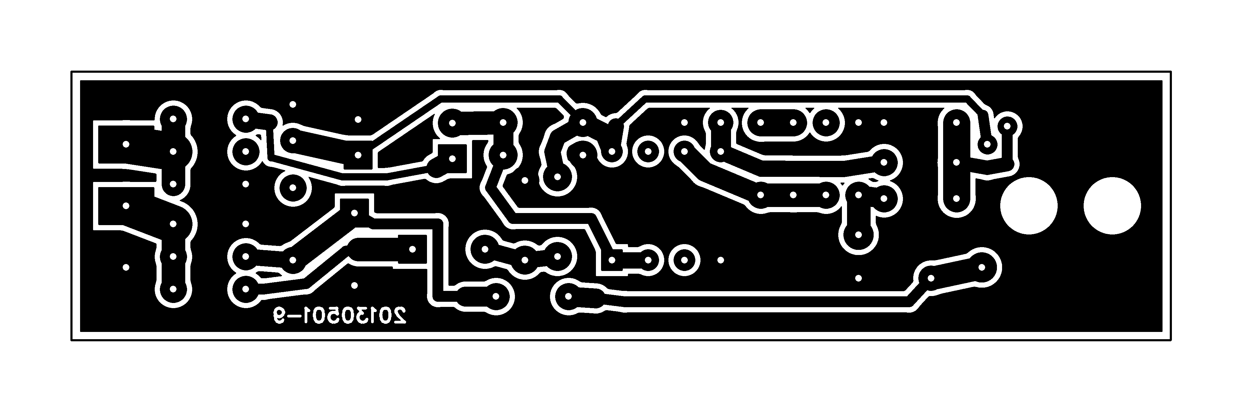
Used single sided:
The bottom-copper mask is designed in such a way, that it can be used for a single sided PCB.
On the single sided PCB you have to install one wire bridge, from C10 (-) to mass (see topsilk).
Assembling (both PCB's):
The input circuitry is extremely high Z.
Prevent damage to T1 and IC1. First connect the mass connection of the soldering iron, AND YOUR BODY, to the mass plane of the PCB.
Press a ceramic feed-through insulator on both places marked "ins".
Solder C1 floating onto both "ins".
Bend the gate leg of T1.
Solder the S and D legs of T1 in the PCB so, that T1 is ca. 5mm free from the PCB.
Solder gate leg of T1 into "ins".
Bend one wire of R2 and solder it in the PCB. The other wire can be soldered on one "ins".
Bend one wire of R1 and solder it in the PCB. The other wire can be soldered on the other "ins".
Solder all other components, starting with all resistors.
Solder IC1 directly into the PCB (do not use a IC socket).
The "cold" connection of the capsule should be soldered to the mass plane near T1.
The "hot" connection of the capsule should be connected to R1.
The diodes can be mounted vertically too.
After testing :
Make the PCB rugged. Glue all capacitors with their bodies (not the connections) onto the PCB or to another component.
Component details.
In this kind of critical and low noise circuits, SMD component should NEVER be used (exept semi conductors like ICs).
C7,8,9,10 must be electrolytic condensers, NOT tantalum.
For all other capacitors, FOIL types MUST be used.
Most ceramic type capacitors generate harmonic and IM distortion when connected to DC and/or AC voltages (see manufacturers specs). They can jump in capacitance value (generating
pop noises). They have a unwanted high temperature coëfficient. This can lead to unwanted unbalance.
For best results use PAIRED foil capacitors. Measure them using a cheap digital multi meter.
Metalfilm resistors are preferred for lower noise and no need for pairing them, as 0.1% tolerances are readily available.
For a wide (down to 10Hz) frequency response, and the lowest noise level, the 500 Meg Ohm input impedance is critical.
The input circuit of EVERY condenser microphone is very sensitive for dirt and moisture.
Keep C1, R1, R2 and T1 clean and dry. Do not touch them with bare fingers.
Both opamps inside IC1 are nearly absolutely equal by nature. Their (low) output impedances are equal. The wanted equal impedances on XLR pins 2 and 3 to mass are
easily obtained by using 1% or better resistors for R8, 9, 10, 11.
Resulting simply in very good noise and hum canceling.
| Acceptable max. difference |
For optimum balance around: | |
| R8/R9 | 0,2 Ohm ! | 500Hz |
| R10/R11 | 5% | 500Hz |
| C5/C6 | Foil capacitors, 1/2% | >=10kHz |
| C8/C9 | If possible, small. | <=50Hz |
Check voltages.
For optimal results the following voltages should be checked and corrected :
1. The undistorted max. output with 2kOhm load @1kHz sinus : >= 4Vtt. Check also on 50Hz and 10kHz.
2. The idle DC voltage on IC1-7 should be 5V+-0,5V (adjust R3).
The supply current into IC1 can vary by brand. This can result in different voltages on C7 and C10.
3. C10 must show 25V +- 1V. Correct it by changing R10/11 (they must have equal value !)
4. C7 must show abt. 12V. Correct it by changing R12.
Design details.
FETs and current setting.
IC1 has a very low noise level, because its input is connected to the low impedance source T1.
The noise figure of T1 therefor is intirely responsible for the noiselevel of the whole circuit.
Only a very low noise Jfet is suitable for T1. It shoukd have a noise figure of 5dB @ 1kHz or lower. It must be capable of drawing 1mA drain current with a gate source voltage value lower than -5V.
Candidates:
BF244a (?)
J310 (?)
2N5417
2SK162
2SK163
2SK170 (!) lowest noise figure.
2SK523
2SK533
Optimum setting of T1.
T1 is a source follower in "Class A" with Id=1mA. Its output voltage is therefore 5Vdc. As will be of IC1-7. This value and the supply voltage on IC1-4 will result in the
max. output voltage possible.
REM: different FETs can have different Idss. Measure the voltage at IC1-7 and correct it (if needed) to 5V +-0.5V by changing the value of R3.
Different brands of IC1 also can show different supply currents. Resulting in non-optimal voltages on C10 (25V +-1V) and C7 (12V). This can be corrected by adapting the values of R10/11 (MUST HAVE EQUAL VALUES) and R12.
Why no transformer ?
A good, low distortion, wide band, well balanced output transformer is expensive, still susceptible to hum induction, and bulky. The IC-output in this circuit is simple, cheap
and serves all needs. And is INsensitive to magnetic fields from other transformers and power lines.
Microphone sensitivity.
At C10 is +25V available for use as bias voltage for the capsule. No noisy bias oscillator is needed.
The value of this voltage influences the cartridges sensitivity. Higher voltages result in higher sensitivity and better signal-to-noise ratio, but lower max. spl (earlier
saturation of the mixers input circuitry).
Higher bias voltages demand a separate bias oscillator, and screening to prevent HF radiation into the rest of the electronics.
pa0nhc.