 The antenna circuit.
With L1 = 20 uH for 80m use :
- it needs 103 pF capacitance for resonance at 3.5 MHz.
- it needs 88 pF capacitance for resonance at 3.8 MHz.
The needed capacitance variation is therefore 15 pF.
| << |
Adapting the tuning range |
(Copyright) The use, copy and modification of all info on this site is only permitted for non-commercial purposes and thereby explicitly mentioning my radio amateur call sign "PA0NHC" as the original writer / designer / photographer /publisher.
The tuning pot meter R15 must be a log. type of good quality. Use a large tuning knob for easy scale drawing.
Two 3W zener diodes (D105 and D106) limit the supply voltage for Vr2 to abt. 33V, in case the connection between the antenna and the tuner is broken. They also reduce the dissipation of Vr2 when low tuning voltages are set.
In the prototype, the tuning range is defined from 3.48MHz to 3.82MHz.
With trimmer R15b the highest tunable frequency ( and the frequency tuning range) can be reduced.
The antenna circuit.
With L1 = 20 uH for 80m use :
- it needs 103 pF capacitance for resonance at 3.5 MHz.
- it needs 88 pF capacitance for resonance at 3.8 MHz.
The needed capacitance variation is therefore 15 pF.
Zener diode D5 in the antenna unit defines a fixed voltage difference between
supply voltage and the actual tuning voltage.
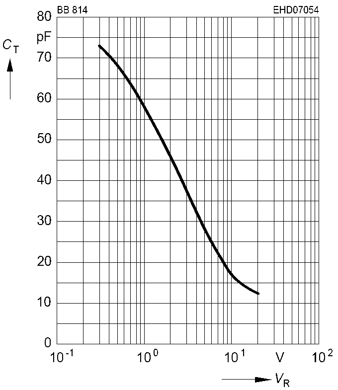
The supply voltage variation is set to between 14V and 19V.
The tuning voltage therefore is ((14 V to 19 V) - 13 V) = 1V to 6V.
The capacitances of both varicap diodes in the BB814 then vary between 58 pF and
25 pF.
As both diodes are connected in (anti-) series, the resulting capacitance variation is between 29 pF and 12.5 pF, that is 16.5
pF variation.
REM : a BB804 is similair to the BB814, but with a slightly less capacitance
variation.
The stray capacitance of L1 + PCB is estimated to 13 pF.
(C11 / C12 / C12a) should therefore resemble (88 pF - 13 pF) = 75 pF.
With 50 pF trimmer C11 adjusted halfway, C12 / C12a should resemble (75 pF - 25 pF)
= 50 pF.
Chosen standard values for C12 and C12a are therefore 100 pF NP0 / C0G.
Adapting the tuning range.
With the here used ferrite rod (Ui=125), tuning to another frequency band
(everywhere between 100 kHz and 21MHz) is possible by :
- changing the self inductance (number of turns) of L1
- and / or changing the values of C12 and C12a.
The fixed voltage difference between supply
voltage and tuning voltage, set by D5 is 13V.
In the antenna unit trimmer C11 is used to adjust the antenna coil to the lowest
tune able
frequency.
To avoid IMD generation in the varicap diodes, the minimum useable tuning voltage is
abt. 1V.
The minimal allowed output voltage of VR2 is therefore (13 + 1
) = 14 Vdc.
The maximal allowed tuning voltage for a BB814 is 18V.
The maximal allowed output voltage of VR2 is therefore (13 + 18) = 31 Vdc.
Measure the tuning voltage on R16 in the antenna
unit.
Turn R15 fully CCW. The tuning voltage should be not lower than 1.0V.
This voltage could differ, when the zener voltage of D5 differs from 13 V.
This voltage can be corrected by changing the output voltage from the tuner
unit. Then change the value of R14a. The change is 1V / kOhm.
Turn R15 fully CW. The tuning voltage should be
abt. 7.0 V.
This voltage can be corrected by changing the output voltage from the tuner
unit. Then change the setting of R15b. If needed, also change R15a.
For a maximal possible tuning range, and a
maximal allowable varicap diode voltage of 18V :
Exchange potmeter R15 for 20 kOhms log, and exchange R15a for
180 kOhms.
The tuning range could further be enlarged, by soldering an extra variacap diode pair BB814 on top of (in parallel to) D3.