|
|
In fig. 1 is allready 20dB isolation presumed, by using a circulator or separate antennas.
From fig.1 can be seen, that beside the 20dB from the circulator or antenna, at least 50dB more is needed at the unwanted frequency in the receive path, and at least 60dB more at the transmit path.
On two metres the difference between transmit- and receive frequencies ("the shift") is only 0.4% (0.6MHz). At 70cms even less, 0.36% (1.6MHz). In the filter very high Q is needed, to achieve enough isolation combined with minimal losses on the pass frequency. These high Qs only are possible by using several (coaxial) resonators in various modes.
| pa0nhc: When catalogs of Kathrein and Procom are studied can be concluded, that these stringent amateur-demands are hard to fullfill.
Procomm cannot deliver a dulpexfilter for the 2mtrs amateur band. The filters they can deliver, have far to much losses. One usable filter for 70cms is not in production anymore, as they could not fullfill the specs (the filter had to much loss, or was not stable). Of all the filters Kathrein makes, only ONE type is usable for the 2mtrs and 70cms amateurbands. They are exellent (30-35dB isolation and only 0.5dB insertion loss per cavity, and very stable), but big and therefore very cosly. They are very rare on the second hand market. If a more sensible (wider) separation between Tx and Rx frequencies could be used, it should be far more easy and cheap to purchase or make a repeater duplexfilter. Other problems, like sideband noise, will be less difficult too. But no, HAMS had to do it the hard way. I wonder: those who desided, did they build repeaters too? |
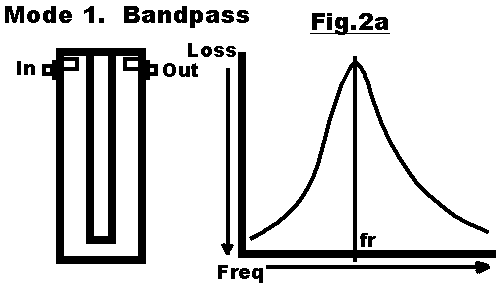
Types and modes of coaxiale cavity resonators.
Mode 1. Bandpass.
|
|
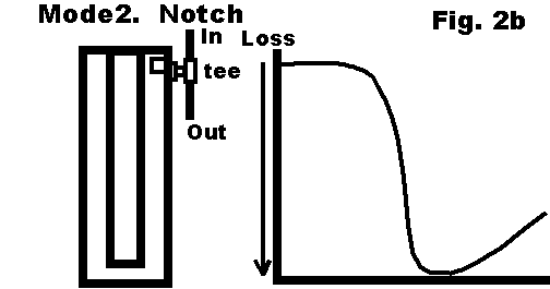
Mode 2. Notch
|
|
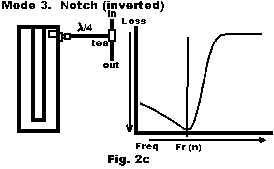
Mode 3. Notch (inverted).
|
|
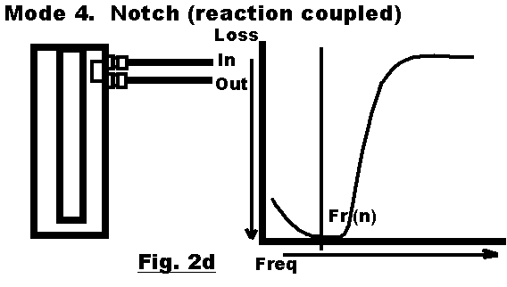
Mode 3 en 4 make the same "inverted notch". In practice, the "reaction coupled notch" is easier to realyse, has a deeper notch, and only slightly higher insertion loss on the pass frequency.
Mode 4. Notch (reaction coupled)
|
|
Specs.
From a good design the following specs can be expected:
| Losses at pass frequency | <= 0,5dB per cavity. |
| Isolation | > 20dB per cavity. |
| pa0nhc: In the home made filter of pi3rtd, a different construction is used (with a C or L connected between the in- and output links). Every
notch-cavity, including all connection cables, has max. abt. 1.25dB insertion loss, and 30dB isolation or more.
The completed filter (2x4cavities) is very cheap to construct, has an insertion loss of <= 5dB, and an isolation of >=100dB. It also provides extra selectivity, as most frequencies outside the pass frequencies are suppressed by more than 30dB, thanks to the use of extra bandpass cavities in the Rx and Tx paths. This also reduces the sidebandnoise from the transmitter. No circulator is needed, as the isolation of the filter is more than enough. (Circulators can make intermod, or mix noise sidebands into the receiverpath, degrading receiver sensitivity). Compare those properties and the price with commercial avelable filters, and other constructions! |