
| << |
Antenna
construction. |
NEW choke
construction (20200614).
Feeder common mode problems cured. (20200614)
Antenna dimensions.
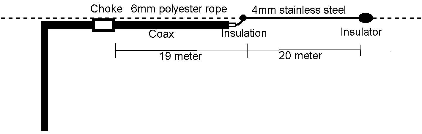
The given dimensions are for a 80m band dipole.
Do use pre-streched polyester
rope (flags line), as it will not change much in length when pulling forces are applied to
it, AND it is UV proof.
It is used to :
- Strech the steel wire
- Support the coax.
- Support the choke.
Nylon is NOT UV proof.
Antenna coax.
The coax cable part of the dipole carries two different RF cutrents :
1. RF current at the inside of the coax from transmitter towardsthe antenna
feedpoint.
2. RF current at the outside of the screening running in the opposite direction
from the dipole feed point toward the antenna choke at the radiator end.
Clearly these currents should be separated as good as possible.
Which can be achieved by using double screened coax cable for the antenna coax
half, and for choke construction.
The for the dipole part used coax
could be :
- 5mm RG300 PTFE silver plated, double screening and small bending radius,
- 5mm RG223/U silver plated, double screening and small bending
radius,
- 5mm Belden H155 double screening and small bending
radius, moist resist foam dielectric
- 7mm AirCell 7 with foam dielectric and braid + foil screening (or
equivalent),
- 11mm RG214 silver plated and double screening.
For the antenna choke and feeder chokes should be used 5mm RG300, RG223/U, H155.
These coaxes can all withstand at least
2 kV between center and screening, which is enough compared to the estimated 320
Vpeak voltage at the dipole ends, using 100W power.
Thick coax is heavy, and pulling forces onto the rope and the supporting antenna
points are much larger.
The choke and coaxes should ONLY be connected using water proof N- male and female connectors, covered with a thin layer of Vaseline during connecting.
Forces.
Do not attempt to pull the antenna into a straight line. It is impossible.
Use a max. pulling force of 33 % of the polyester line and steel wire
specified max force. Then you have good reserve.
Or use thicker rope, steel wire and clamp.
It is normal that the antenna sways
a bit during strong winds. Don't worry as long as the antenna support points can
handle it.
When using a tree as support, the antenna end should be connected to the tree
via a moving system like :
- Weather proof rubber bands or
- The end rope running over a pulley down to a weight (bucker with sand)
or
- A compression spring (used in ships radio long wire antennas).
Radiator lengths.
The length of the coax part between
the dipole midpoint and the antenna choke, is shorter than the stainless steel
wire part at the right.
The reason for this difference is :
- The stray capacitance of the choke,
and
- The thicker coax has more stray capacitance to the surroundings.
It is an effort to keep the dipole fully balanced, eliminating the loading
capacitance differences.
With these dimensions, the antenna
should be useable on all 160 m - 20 m bands.
On 80m should the antenna have low VSWR, as the antenna resonates there.
With the possibility of using 400W power, as due to the absence of heavy
standing waves inside the coax, coax losses and heating are little..
For the USA 80m band (3800 kHz) shorten both dipole halves a bit to 18.25 m coax, and 19.2 m steel wire.
The other bands need a tuner, as the
dipole antenna is out of resonance, and the impedance at the transmitter side of
the feeder is unknown.
But the antenna stays always BALANCED, and with feeder CMCs installed, NO COMMON
MODE problems should occur..
TIP :
Make to begin, the steel wire part 1m
longer.
Test on 80m where the WSWR is the lowest.
Estimate the needed shorting of the wire.
The coax length cannot be changed easilly.
Therefore :
- If the resonance frequency is for instance 5% to low, shorten the
wire by 5 %.
The coax must have a little slack in
respect to the rope, as the rope will stretch a little when pulling it, and no
stretching forces must be on the coax.
The coax is supported by the rope, by tie wraps which are going through
the rope, to prevent sliding along the rope.
Press at distances of about 50 cm a sharp pointed 6mm pin through the rope to
create a hole, and insert there tie wraps.
Wrap the tie wrap TWICE around the coax and tighten. Twice to create more
grip without damage to the coax by over tightening it.
Remove excess tie wrap
end.
The dipole center.
At the dipole center, the coax screening is ending. But the coax center conductor must there be connected to the steel wire dipole half. And there must be ample insulation between coax screening and center conductor. The internal coax insulation core can be used for that purpose. Create 20 mm free coax internal insulation length.
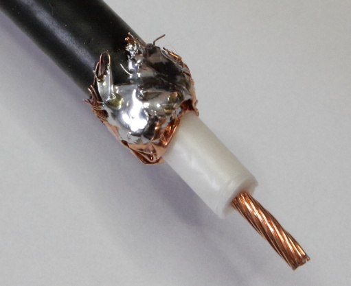
The end of the dipole coax screening.
 Train
yourself the following procedures at forehand on small pieces coax, rope wire
and clamp :
Train
yourself the following procedures at forehand on small pieces coax, rope wire
and clamp :
- Cutting and soldering the screening.
- Connecting the whole dipole center.
- Waterproofing and crimping the dipole center.
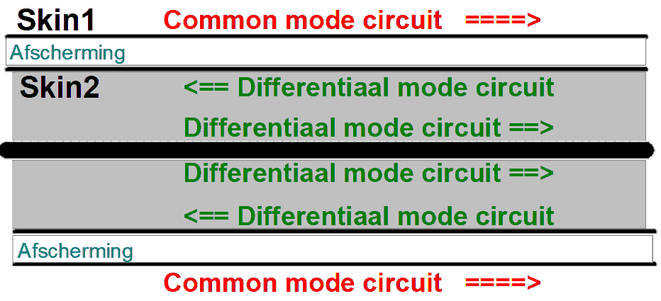
Every coax screening contains two FULLY FROM EACH OTHER INSLULATED HIGH
FREQUENCY SURFACES (skins).
The
INNER surface of the screening (Skin2) belongs to the differential mode
circuit,
and CANNOT radiate power. It can only transport power from transmitter to
antenna feed point.
The OUTER surface of the screening (Skin1) belongs to the common mode
circuit, which WILL RADIATE power.
At the center point of the antenna, Skin2 has therefore to be positively connected to Skin1, so the RF power can reach the common mode circuit and be radiated. Soldering prevents corrosion problems.
- Fold back the screening.
- Solder the screening inside through with the screening outside.
When using coax including breaded
screening AND foil screening :
- Fold back the braid,
- Fold back the foil.
- Solder the exposed foil inside to the braid outside.
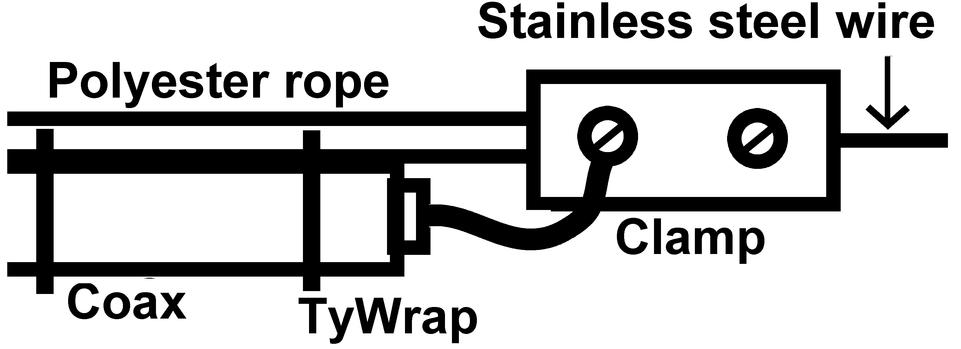 Connecting the dipole center.
The supporting polyester rope and the dipole
wire can be mechanically connected using a 5 mm stainless steel wire clamp with
two clamping screws.
Securing against sliding.
Before connecting, slip a piece of
crimp hose (which mechanically fits over the whole connection) over the steel wire.
Make a knot in the rope end, and seal it by melting. This knot
should just come outside the right end of the clamp in the drawing. It protects
the rope against sliding out of the clamp.
The steel wire should also go through the full length of the clamp with just
enough extra length outside the clamp.
Put a firmly crimped solder eye over the wire end,
and connect it under the right hand clamp nut.
Pull the wire until the extra end is shortest en bend around the clamp end. This
also will protect against sliding out.
Firmly close the clamp, and be sure that the steel wire makes contact with it and with the coax central conductor.
The coax center conductor can be connected using a solder-eye under the left hand clamp screw.
Be sure there is enough insulating space between the coax screening end, and the clamp.
Water proofing the dipole center.
When the connection is ready and carefully inspected :
- Heath the whole center construction a bit at thermal glue melting
temperature and
- Cover the whole center construction with thermal glue, especially the
coax end
- Quickly shift the crimp hose over the connection and
- Starting at the middle of the crimp hose, going towards both ends,
keep
crimping until
- The whole connection is fully crimped, thereby thermal glue pressing out from the
ends, thus fully sealing the center connection.
- Let cool completely.
In stead of thermal glue, you also could use petroleum gel
(Vaseline) to cover the connection before crimping.
After crimping, wipe off excess Vaseline.
VSWR.
If a very unhandy VSWR occurs on one of the
other bands, just lengthen the coax feeder a bit (insert an extra piece of coax
with connectors), to shift the coax-end-impedance to a more manageable VSWR.
Do not worry to much about coax losses due to high VSWR on lower bands, as the frequency is rather low as losses will be too.
For reception, the losses on 14 MHz are UNimportant, as received noise will be the same amount weaker too, and signal-to-noise ratio is unaltered.
High power is restricted by high
voltage or current locations inside the coa with high VSWR. Most coaxes can
handle at least 2kV.
High currents can be noticed by locally coax temperature rise. PTFE coax and
wire can handle 200C.
The ferrite cores max. temperature are 120C, and coil resonance frequencies
will then shift down. Good for 160m, less good 20m.
But with the advised coil constructions, ferrite core warming up
by RF is not expected.
Statics discharge.
There is purposely no parallel choke nor parallel resistor over the dipole
center connection. It could negatively influence a Hi-Z antenna feed point impedance.
The dipole halves are therefore fully insulated from each other
However, possible static charges on
the dipole wire part, must be able to flow to the ground connection of the tuner,
and from there to safety ground.
Check therefore if the tuner output center pin is connected to the tuner ground.
If not, connect a 22 kOhms wire wound 5W resistor over the antenna connection of
the tuner (or transceiver).