|
On the lowest position : |
| << |
Properties of a 1/4 lambda loop. |
|
|
On the lowest position : |
In a 1/4 lambda circumference loop, is the RF loop current near the tuning capacitor much smaller than in the center of the loop. In
other words: the loop current value is NOT constant around.
Simulation shows that as a result :
- In the radiation pattern is a minimum at the position of the tuning capacitor.
- In the radiation pattern is a maximum near the RF current maximum.
Conclusion:
When positioning the tuning capacitor at the lowest point :
1. The highest loop part radiates. Good for maximal efficiency.
2. That radiation is towards the sky, good for NVIS.
3. The minimum radiation (and sensitivity) is towards the roof. Resulting in less noise reception and less RF in the building.
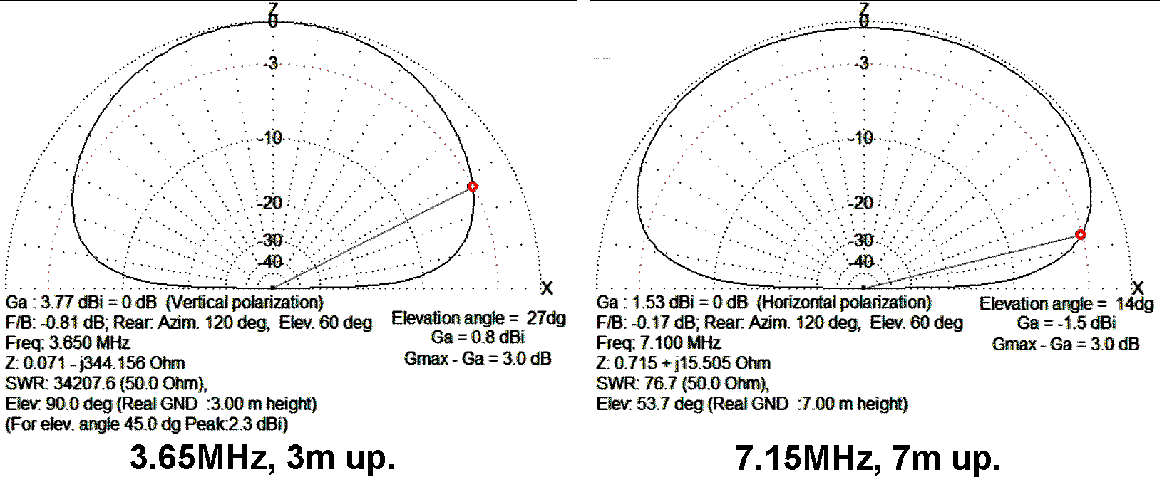
According to 66pacific.com
, a 10m circumference loop with only 1cm thick radiator is already efficient on 7.1MHz .
However, if such a a 10m circumference loop
is tuned to 3.65MHz, it operates as a 1/8 lambda loop.
In such a situation the use of a thick
radiator (>=35 mm) is recommended.
