 My roof surface is abt. 7 x 10m, made of concrete, and contains mains power cabling, TV coax and telephone line.
It is insulated with thick foam, and covered by a plastic sheet and gravel.
My roof surface is abt. 7 x 10m, made of concrete, and contains mains power cabling, TV coax and telephone line.
It is insulated with thick foam, and covered by a plastic sheet and gravel. | << |
Installing
the all-weather outdoor 40 / 60 / 80m TXloop. |
My roof surface is abt. 7 x 10m, made of concrete, and contains mains power cabling, TV coax and telephone line.
It is insulated with thick foam, and covered by a plastic sheet and gravel.
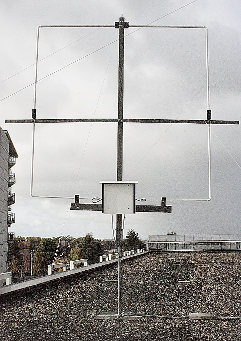
The loop radiator is electrically floating, and forced to balance by connecting the "split stator" tuning capacitor shaft to ground. The goal is to make it more insensitive for reception of E-field noises, and to reduce BCI and TVI completely.
As the loop radiator does not carry higher RF voltages than 1.1 kVpeak, the radiator insulators could be made from pieces 6mm Trespa plate (or "perspex"or "plexiglass"). Never was any influence from rain or humidity noticed.
The wooden loop mast is clamped to the standpipe of a satellite dish base foot, using muffler clamps. All wood is painted twice with outdoor wood paint. TIP : better use rot-free and paint-free garden composite material.
The satellite dish base is 60cm x 60cm x 1.2m, weighted with four 8 kg. concrete tiles to stabilize it against rotation
Three 5mm
pre-stretched polyester flags lines guy lines are connected to the mast top. Two
more polyester guy wires connected to the ends of the central horizontal wooden beam
prevent
"no-shaking".
TIP : Pre-stretched polyester flags line does not become brittle in UV environments, and will not
stretch much at heavy loads. Do not use nylon rope as it stretches and
deteriorates due to UV light.
Stainless steel hardware which comes in contact with aluminum, was protected against corrosion with spray Tectyl. TIP : try to use ONLY stainless steel hardware !
|
|
At
several places concrete tiles are loosely placed over the cables to stabilize
them in windy conditions.
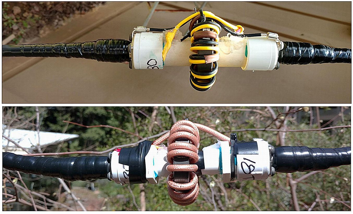
Common Mode Chokes must be installed
over the cables. They limit common mode
currents, and prevent common mode resonance. Common Mode currents influence the loop radiation pattern, and
couple common mode noises
into the loop antenna or the radio..
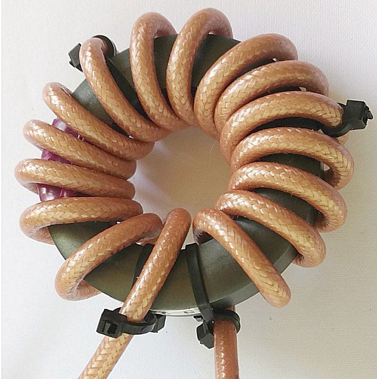
Wind 61mm #31 cores (FairRite 2631803802) with
16 turns coax or command cable.
Install such chokes :
1 One near
the tuning box over the coax
2 One near the transmitter end of the feeder coax.
3 In-between them at maximal distances of 5meter (= 1/8 lambda for the
highest band 40m).
These 61mm
MIX#31 cores are CHEAP (less than 5 Euros nett each) in orders over 50 Euro at Mouser.com etc.
See the photo on the right how to prevent
unwinding of the cable. Especially when winding slippery PTFE coax.
Fix as follows the coax four times to the core with black (UV resist) "tywraps"
:
1. First loosely connect a tywarp around the ferrite core.
2. Then push a second tywrap between the first tywrap and the ferrite core
3. Close the second tywrap around the coax.
4. Tighten the first tywrap around the ferrite core.
Below such common mode
chokes for inserting into a feeder coax.
HF connections are made with watertight male N-plugs on the coaxes
and watertight female N-busses in the PPE tube.
This costs more money for connectors, but installing cable parts and CMCs is much
easier :
- Cable parts and CMCs can be ready made at forehand.
- Installation and repair can later done during good weather, and is much easier
and faster.