|
|
||
|
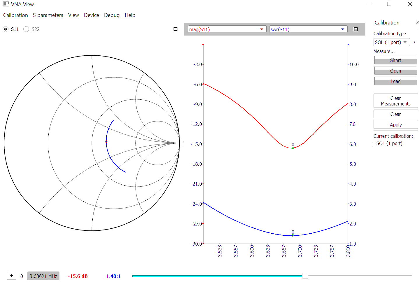
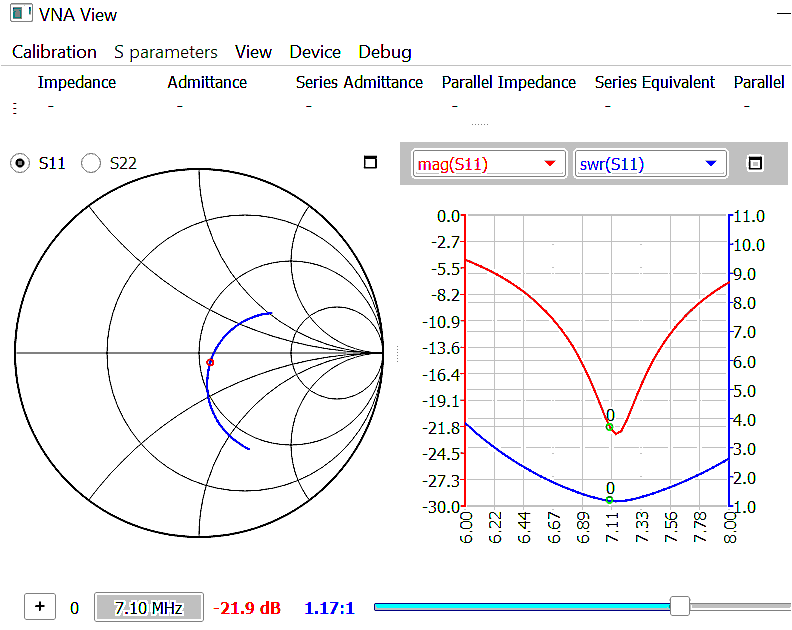
Measurements performed with a calibrated NanoVNA V4 and VNA_QT software.
Fine adjustement of the
40m series resonance frequency can easiest be done, |
| << |
How to adjust the value of the series tuning capacitors.
|
The precise values for C40 and C80 for your matchbox must be measured and adjusted by yourself.
Due to
the tolerances in the specifications of the
ferrite of the core (Ui = 125 +-25%), the capacitors (+- 20%), the winding quality of the
transformer (wound tight or looser, other wire size), and the length and
thickness of the connecting wires between matchbox and loop, your optimal capacitor values
for C40 and C80 could be a bit different from those published here.
The length of the connecting wires with the antenna MUST be as short as possible, as they
determain the total series inductance and the needed capacitor values of the
matching circuit. ALSO : be aware, that these connecting wires should NOT act as
a part of the radiator.They only must act as a balanced connection between
transformer and loop. Therefore : use for the connecting wire a kind of twin
lead, for instance very thick speaker wire. Do separate these wires for as short
as possible length. Leave as much length mechanically connected together. Then
this wire pair is balanced, and will not radiate nor receive (noise) energy, and
has no influence to the resonance frequency of the loop.
Before measuring capacitance values,
be sure that the used length of the connecting output wires
are definitively correct for installing the matchbox at the antenna.
The
length of the connecting wires cannot be changed afterwards, without the need to
re-adjusting the series
resonance capacitors.
As
the transformer has a limited possibilities of transformation ratios (the
secondairy winding can only be a whole number of turns), only nearly
perfect match can be achieved.
The VSWR at the transmitter can also be influenced by the length of the coax
feeder, and at the working frequency resonating metal objects near the loop
antenna. Theoretically best electrical coax feeder length is around 40m, as this is a
half wavelngth for 80m, and a full wavelength for 40m operation. The coax will
then not transform the antenna VSWR. Other lenghts can of course be used, but VSWR noted at the transmitter can then differ from the VSWR
noted at the antenna, as some impedance transformation will occur.
But do not worry to much about coax losses, they remain very low at these low frequency bands, even with some mismatch. The largest influence of higher VSWR is that the transmitter PA cannot accept it, and will be overheathet or even shuts down. A best achiveable VSWR ratio at loop resonance of ca. 1.2 is normal (reflection damping between 15dB to 30 dB). VSWR of up to 1:1.5 is normally acceptable.
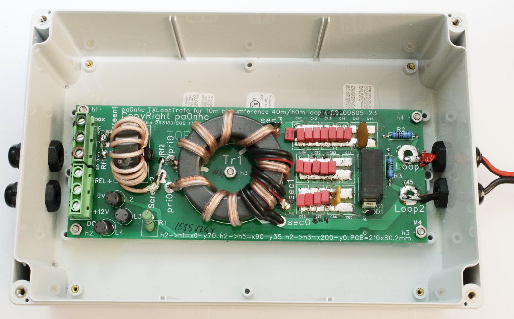
Numbers and types of capacitors to install :
40m : (8x)100pF Wima 630V FKP2 or MICA 500V (~ 806 pF total).
80m : (8x) 680pF Wima 630V FKP2 (+ 240p Mica + 68p Mica 500V, ~ 5748 pF
total)
FKP2 and MICA capacitors have low losses and are stable.
RF currents in the trafo and the loop :
The transformer ratios of 9:1 and 9:3 are optimal for
this 10m circumference loop for 80m and 40m band operation.
10m circumference loop feedpoint impedances at loop resonance are about 0,6 Ohm
at 80m, and 5,5 Ohm at 40m.
Current calulations for 5.5 ohms load at 40m, and 0.625 Ohms load at 80m, and 400W
power :
The calculated RF current in C40 is 8.53 Arms and the RF voltage over C40 is
242 Vrms. I = Abt. 1A per each capacitor.
The calculated RF current in C80 is 25.3 Arms and the RF voltage over C80 is 191.8
Vrms. I = Abt.
2.5A per each capacitor.
CHECK the manufacturer data of the by you used capacitors. Be sure the used capacitors can handle these
large RF
voltages
and large currents at the operating
frequency.
New matchbox with new PC:
|
|
||
|
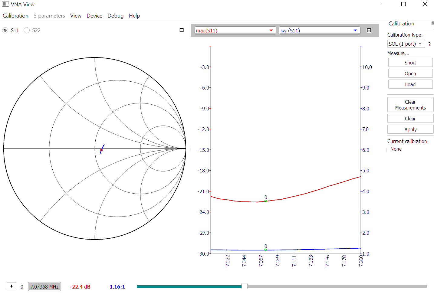
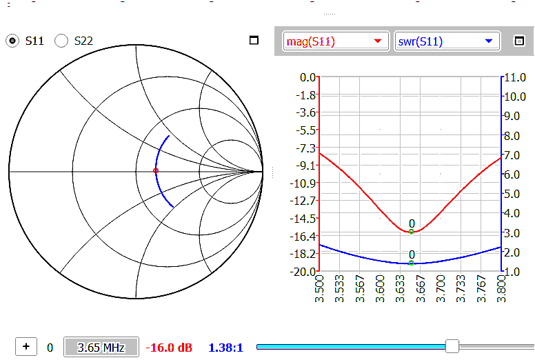
Measurements performed with a calibrated NanoVNA V4 and VNA_QT software.
Fine adjustement of the
40m series resonance frequency can easiest be done, |
Simple capacitor
adjustements using a NanoVNA :
- Connect four (4) 22 Ohm 1/4W 1% metalfilm resistors in parallel for the 40m band, or
sixteen (16) 1/4 W 10 Ohm 1% metalfilm resistors in parallel for 80m band
- Connect both DEFINITIVE LENGTH AND THICKNESS connecting wires to the PCB.
Use for instance a thick piece of
speakerwire and leave it as long as possible mechanically be bonded together.
- Connect the appropriate tedst load resistor set (40m or 80m) to the ends
of these connecting wires.
- Connect CH0 of a NanoVNA to the input of the PCB, using a short 50
Ohms coax cable.
- Set the VNA "Center" frequency to the band center.
- Set the VNA "Span" to 4MHz for 80m band or 6MHz for 50m
band.
- Set the VNA "Mode" to "S11 VSWR".
- Observe at which frequency the VSWR is minimal. (or reflection damping is maximal.)
- Calculate the optimal capacitor value for resonance at band center as in
"adjustment tips" is demonstrated.
- Correct the total value of the series capacitor in question.
- Check VSWR at band center. It should be < 1.2 .
After installing
and connecting the
match box to the loop, check VSWR at band-ends and band-mid :
at the antenna site, and
at the
transmitter site.
At transmitter site, the noticed bandwidth will be influenced by the electrical length of the coax
feeder
Remember : a 1/4 wave long coax will act as transmission line transformer.
Capacitor adjustment tips :
To high
resonance frequency ? => enlarge the total series resonance capacitor
value.
To low resonance frequency ? => decrease the total series resonance capacitor
value.
As the transformer leakage inductance is a fixed value, the capacitor
value has to change quadratic.
Relative capacitance value change =
relative [ -- (frequency change)2]
For instance :
If you need to change the resonance frequency to 0.9 times
lower (10 % lower) :
- The capacitor value changes to (1.1)2
or 1.21 times the last value, or 21% higher.
If you need to change the resonance frequency to 1.1 times
higher (10 % higher) :
- The capacitor value changes to (0.9)2
or 0.81 times the last value, or 19% lower.
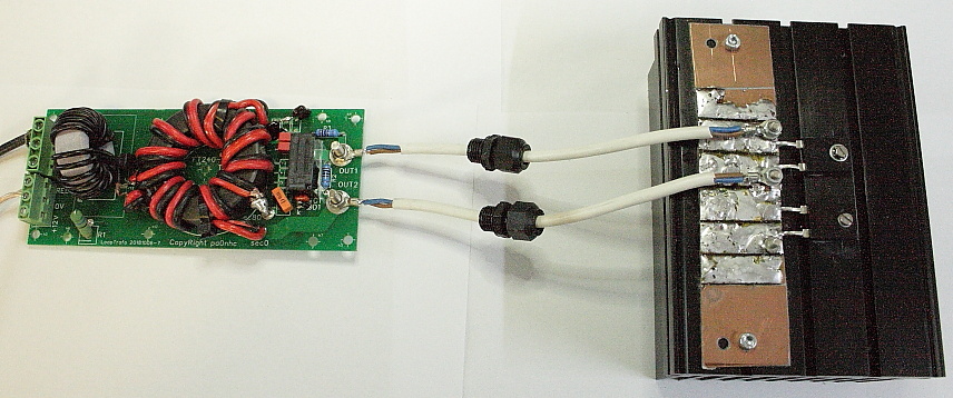
Prototype matchbox CW endurance test.
|
|
||
|
Temperatures measured on the proto type.
Temperatures after
10min. continues 100W (40m) carrier, connected to RF load 5.5 ohm :
- no change in SWR results (!)
- load resistor body temp. 105C.
- cooling profile temp. 65C.
- 80m transformer sec. winding temp abt. 50C.
- C40 abt. 43C.
Why connecting a lot of capacitors in parallel :
- Only a small part of the total RF current
flows in each capacitor.
- Resulting in less capacitor temperature rise.
- The value of each capacitor is smaller.
- Their voltage and current handling is higher.
- The resonance frequency is easier to adjust.
The new PCB is designed a variety of capaitor types, even SMD.
By soldering
capacitors to
top and bottom, a lot of mica capacitors can be
placed.
When soldering capacitors onto the bottom, be sure to leave anough
space between PCB bottom and cabinet.
Be sure
that all capacitors can be cooled by airflow.