| << |
The coax feeder, where to place CMC's, grounding,
PIN1 problems and results. |
Feeder.
LZ1AQ used STP for connection between splitter and
antenna amplifier.
Using coax with multiple CMC's (ferrite Common
Mode Chokes), in stead of one
"balanced" pair of UTP wires, makes the prevention of
"PIN1 Problems", and common mode current problems much more effective.
Thin coax enables to wind far more
effective CMC's (11 turns in stead of 5 turns, resulting in 5 times higher
common mode suppression !).
Using split-core #31 material cores
make installing Common Mode
Chokes on long pieces of coax much easier.
So : Best use thin coax RG316 / RG174.
Install at both ends one CMC, and also more in between, with maximal
distances of 3 meters. See "Construction
Details".
The distances between the CMC's should be approximate
1/4 lambda for the highest frequency to listen to.
==> Prevent CMC distances of 1/2 lambda, as this lead to AMPLIFIED common
mode noises in stead of blocking them ! For the highest frequency (30MHz) of
this loop system 1/2 lambda is only 5m. Avoid it.
Prevent ground loops !
ONE point grounding : Ground
the receiver only (or
only the antenna housing).
Prevent "Pin1
problems" !
DO construct a SCREENED loop.
DO use screening metal PCB housings.
DO mount all coax busses in good electrical contact with the OUTSIDE of the metal housings.
DO use full metal busses AND plugs of good quality for RF and for power.
REM : cheap bad quality BNC plugs can cause noise reception problems.
DO install Common Mode Chokes on the
feeder.
You will be rewarded with the best Signal To Noise Ratio
possible in your active loop antenna location.
|
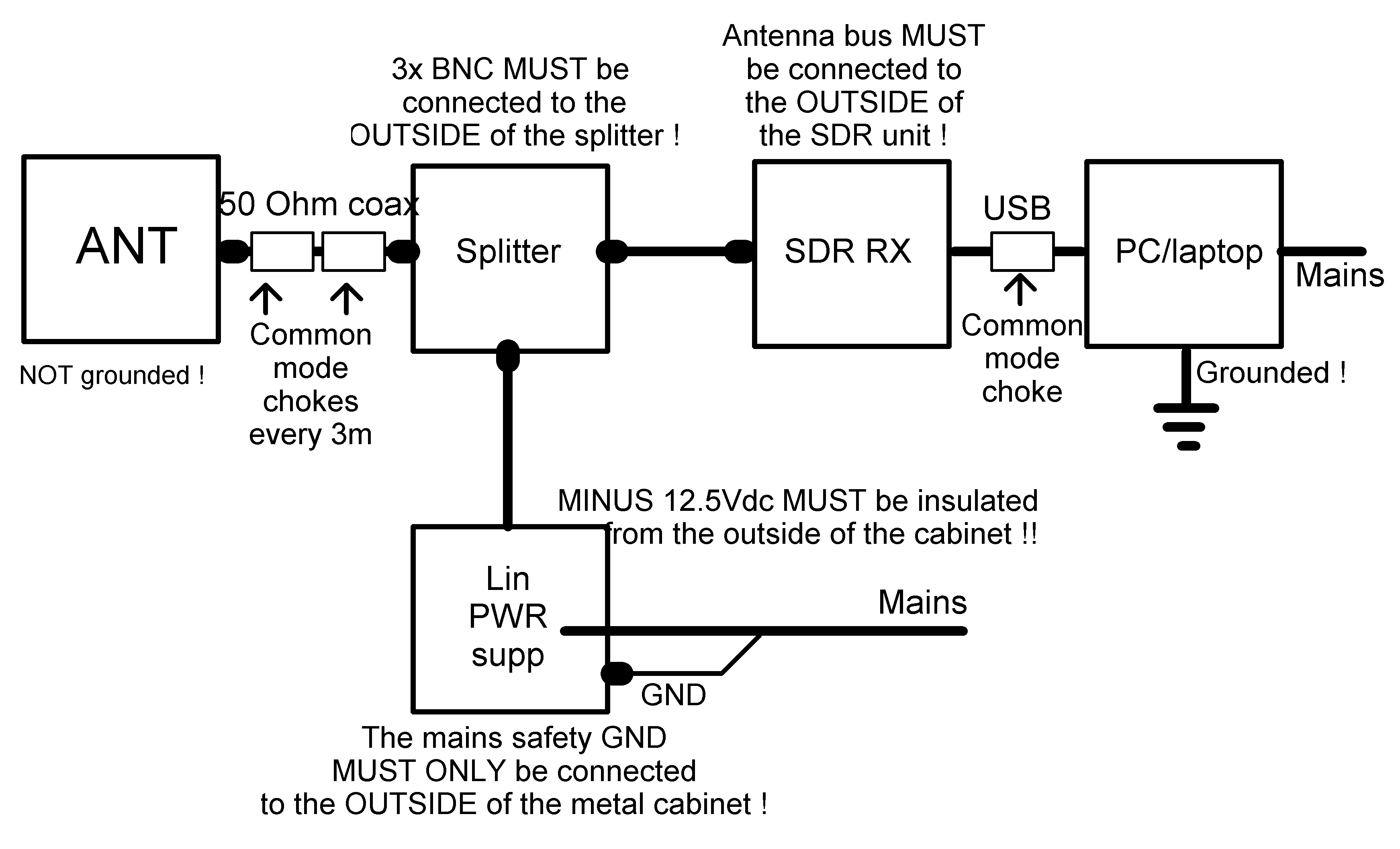
IMPORTANT !
The placement of CMCs, screening and grounding.
ONLY with ALL
these measures can optimal performance be achieved !
A DOT is a connector or
screw in good contact with the OUTSIDE of the screening metal housing.
See also : "De-noising
an external power supply". |
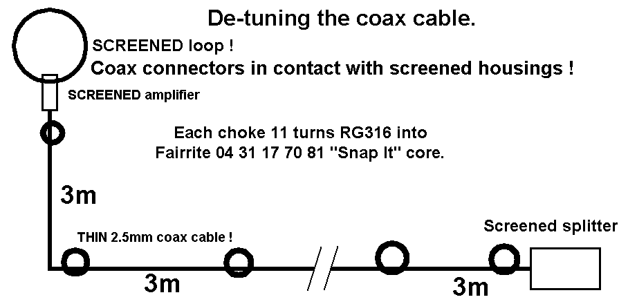
This is the ultimate way, to de-tune
all 1/2 wave common mode resonances on the connecting feeder, to a
frequency ABOVE the highest frequency to listen to.
See also : "Construction
Details". |
Effectiveness.
|
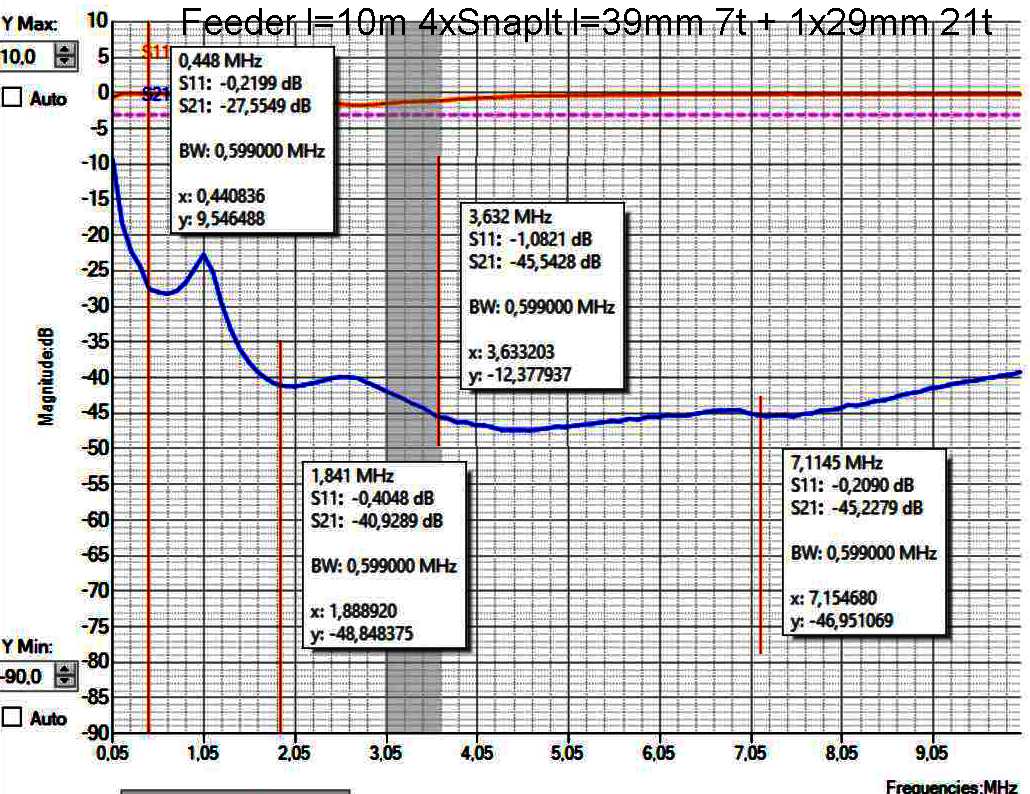
TEST result with NanoVNA.
This is the Common Mode suppression on a 10m long feeder,
with four CMCs between
both feeder ends.
Each CMC is made with a 39mm long FairRite "SnapIt" core, and 7 turns RG58 wound
through them.
(One extra CMC 29mm ring core with 21 turns RG316 wound through
it on antenna end, simulates the balancing effect of antenna
amplifier PCB).
CMCs wound with 11 turns thin coax will give at least 15dB better
suppression.
|
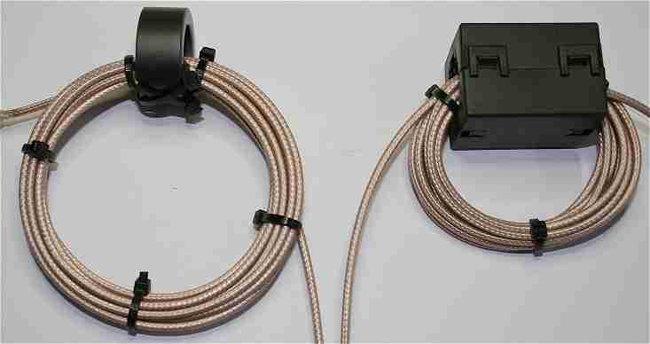
Very good CMC's with 11 turns RG316 PTFE coax.
The FairRite "SnapIt"
core with a 19mm hole at the right, makes installing it on a long piece
of coax easy.
Each CMC costs about 1m
extra coax.
Example : A 15m long coax line must contain 6 CMC's,
and will cost in total about 21m coax. See
"Consruction
Details". |
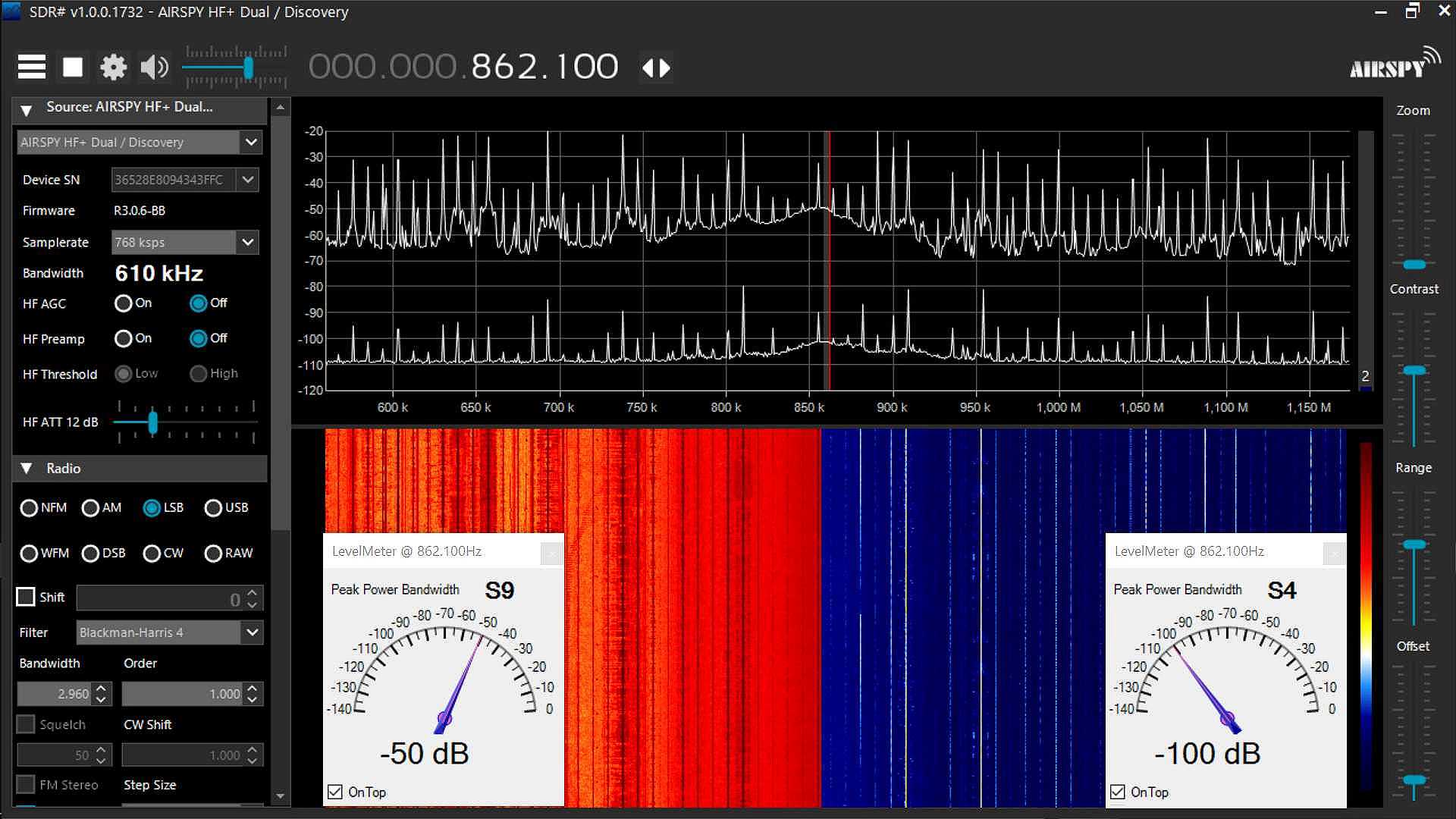
Medium Wave AM Broadcast band. Left = power ON, Right = power off.
Despite that the used CMCs are becoming less effective below 2MHz, due to all
balancing measures, the common mode suppression is still 50 dB at 862 kHz.
The CMCs are, due to their wideband resonance,
most
effective in the 80m amateur band.
When the loop power is switched off,
NO signals are visible.
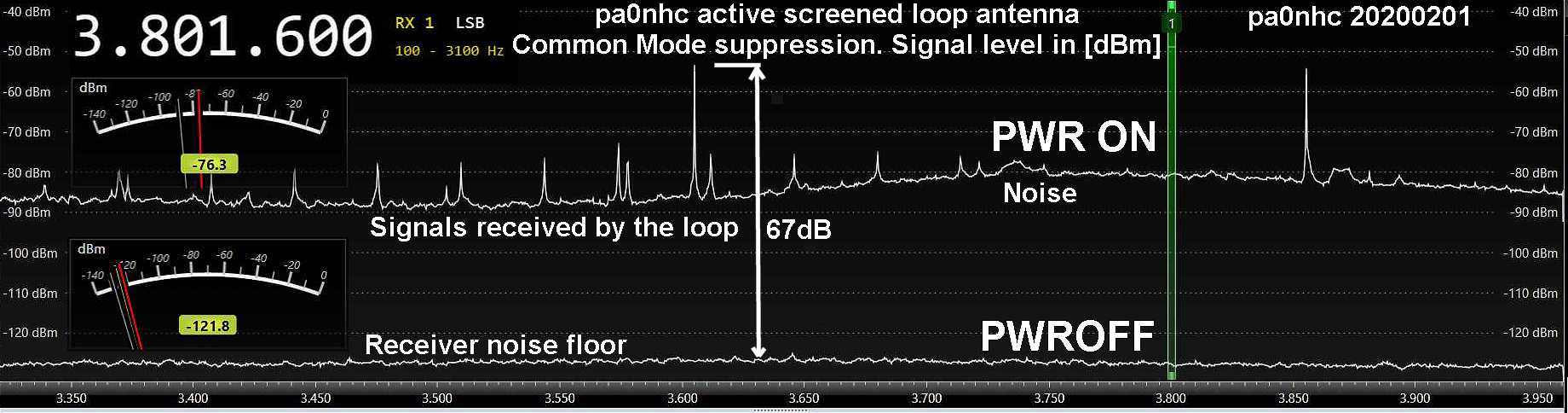
Rem : the 80m band noise level in noise free locations is S6 (-91 dBm).
The strong amateur signal (S9+19dB) at 3603 kHz, and the strong wideband
noise hill around 3800 kHz,
vanish under the receiver noise floor of -121 dBm (S1).
Impressive !