|
|
A
single helix notch filter for the 2m-band.
pa0nhc 2002 07 03.
Correction: 203 07 07. / 20110307 |
This filter is designed to suppress signals
between 155 and 165 MHz, but to pass signals in the 2mtrs amateur band nearly
without attenuation. They can prevent noises, caused by IMD in your receiver,
due to strong out-band signals.
The filters are made from cheap, easy to get
materials. For tuning, measuring-instruments and experience using them is
needed. So this is NOT a beginners project.
What is a helix
resonator and what can it do.
A helix resonator circuit comprises of a coil inside a screening. It has
no discrete tuning condenser. The parasitic capacitance between the coil
windings and the screening is used like this. This "condenser"
has a very small value, and low loss, because the dielectric is made of
air. Consequently, the circuit-Q is large.
The mechanical and electrical properties
of a helix circuits are between "conventional"
parallel-tuned-circuits and coaxial resonators.
Helix circuits mostly have larger
dimensions than parallel-tuned circuits using a discrete tuning
condenser. In modern HAM-equipment helix circuits are not found often,
presumably because they are bigger, and prevent miniaturization. In
professional communication equipment helix band pass filters were used
more often, in order to get good selectivity.
Compared with 1/4 wavelength long coaxial
resonators, helix circuits are smaller, and have therefore lower Q.
Duplex filters of (amateur-) repeaters
with small shift (0,6MHz) therefore need coaxial resonators. In
professional repeaters, using wider shift (4 to 10 MHz), duplex filters
often contain helix resonators. They are smaller, and cost less.
|
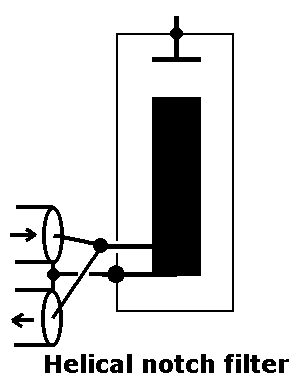
Schema
|
As notch filter.
When experimenting with home-made helix resonators,
i discovered:
- If a tap on the helix is
connected to a transmission line, it becomes a narrow-band absorbing circuit
("notch filter"). The notch can reach a depth of 30-40 dB.
- On a certain lower frequency,
a low SWR and insertion loss is measurable. The frequency-difference between the
notch and pass is called "shift". The shift can be adjusted by
adjusting the coil-tap nearer to, or further away from the mass-connection of
the helix.
- If the helix notch filter is
connected to the transmission line through a 1/4 wave cable piece, the notch
will be below the pass frequency. This behavior is comparable to
that of coaxial resonators.
Needed equipment.
For adjustment of this type of filters you need measuring equipment, and
experience using it. Adjustment is most easy using spectrum analyzer, tracking
generator and directional coupler.
Adjustment is also possible using less
sophisticated equipment. For measuring the frequency characteristics, a 100-200
MHz signal generator with calibrated attenuator, and a receiver for 100-200 MHz
with a good (analog) signal strength meter, can be used.
To measure the insertion loss, and the correct
match to the transmission line at 146 MHz, a good SWR meter, power meter, dummy
load, and a transmitter for 130-146 MHz can be used.
Dimensioning the filter.
During experiments i found, that the way of coupling between transmission line
and the helix resonator had a decisive influence on the properties of the
filter. Studying different ways of coupling and assembling, and the measuring
and comparison of it all, took a lot of time. If you stick to the dimensions i
state here, you will save a lot of time getting good results.
A tuning screw was not used. The filters were
accurately adjusted to a fixed frequency. I you whish, a tuning screw can be
added.
The diameter of the screening, the thickness of
the coil wire, and the amount of stray capacitance between the coil end and the
screening, determine the circuit-Q. The bigger they are, and the smaller the
stray capacitance, the higher the Q, the lower the insertion loss, and the
deeper the notch will be.
According to a nomogram i found in an old book,
the coil has to have a diameter half of that of the screening.
The length of the coil should be twice the diameter of the coil.
The wire diameter should be half of the pitch.
These sizes give good, predictable results.
The filters described here sometimes differ from
these recommendations. This because cheap materials readily available were used.
Above that, the notch filters proved to give
better results using shortest connections possible, and therefore the helix
sometimes had to be positioned out of the center of the can.
Materials:
| 1. |
Clean new paint can 3/4 liters. Diameter x
height = 100 x 115 mm. Higher cans can be used too. |
| 2. |
Tinned copper wire 3mm diameter. |
| 3. |
BNC chassis receptacle, one-hole mounting (PTFE
insulation!). |
| 4. |
Transparent glue cartridge for thermal glue
pistol. |
Construction: See fig.
1 to 4 for details.
Wind a coil from the 3mm copper wire. Diameter 48 mm, pitch 10 mm, 5 turns. Bend
the mass-side sharply at 90 degr. in the direction of the side of the screening.
Both coil-ends will be trimmed later to fit, so leave them long enough.
Drill a hole of 9.5 mm diameter at 25 mm above
the bottom in the side of the can.
Solder the BNC receptacle into the hole. If the
insulation melts, it was not made of PTFE (HI).
Important
construction details:
The shape and length of the mass-end of the coil, and the way the BNC
receptacle is connected to the coil, have big influence on the filter
properties!
Best results are obtained, if the coil end which will be connected to
the screen, is bent 900 with respect to the coil, and if this
end is soldered to the SIDE of the screen in a short way.
The connection between BNC and coil MUST
be AS SHORT AS POSSIBLE. Solder the coil therefore DIRECTLY onto the
upper side of the pin of the BNC, close against the BNC insulation. The
consequence is, that the coil is positioned not in the center of the
can. This proved to have no serious consequences.
Wrong: Should you connect through a short
piece of wire, the notch will be about 10 dB less deep!
Keep enough free space between the top of
the coil, and the side and top lid of the can. This will reduce
stray-capacitance, and detuning when the lid is placed.
|
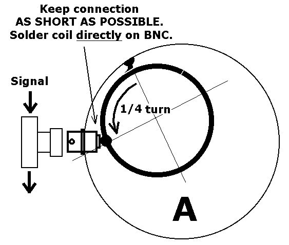
Fig. 1
|
Tap.
The shift can be adjusted, by changing the distance between the tap-point and
the the point where the coil end is bended towards the screen. For details see
fig. 1-4. The table below shows the approximate taps i found:
| Notch frequency (MHz) |
155 |
160 |
164,35 |
Tap on coil, distance
measured
from mass-connection (Turn) |
1/4 |
1/2
*** |
3/4 |
|
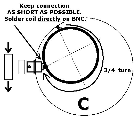
Fig. 3
|
Assembling:
| - |
Cut the mass-connection of the
coil so, that the coil will fit onto the BNC at the correct point, the
mass connection of the coil to the screen, while keeping enough distance
between the coil and the screen. |
| - |
Temporarily put an connector
onto the BNC receptacle. It will cool the insulation, en keeps the pin
centered. |
| - |
Tin the coil, BNC-pin and can at
the appropriate places. |
| - |
Place the coil onto the BNC-pin,
with the mass end of the coil resting to the side of the can.
Temporarily solder the coil onto the pin.
|
| - |
Solder the mass-end of the coil
to the can. |
| - |
Solder the coil to the BNC-pin. |
Another configuration:
*** If the tap has to be 1/2 turn,
a short connection between the BNC and the coil is impossible. You now have two
possibilities:
| 1. |
In that case, solder a second BNC
exactly opposite to the first. See fig. 2.
Keep the whole structure further
SYMMETRICAL. This way, the influence of the connecting wire will
be "balanced out", and a notch depth of nearly 40 dB
will still be possible.
|
| |
Interconnect both BNC-pins using a
thick piece of wire. |
| |
Solder the coil exactly centric
in the screening, with the mass connection onto one BNC-outer.
The coil has to rest onto the connection wire. |
| |
Solder the connection wire to the
coil. |
or
| 2. |
Bend the mass end of the coil at 90
degr. in the direction of the bottom. |
| |
Solder the coil at the 1/2 turn
tap-point onto the BNC-pin. |
| |
Solder the mass connection of the
coil onto the bottom (see foto 1). |
|
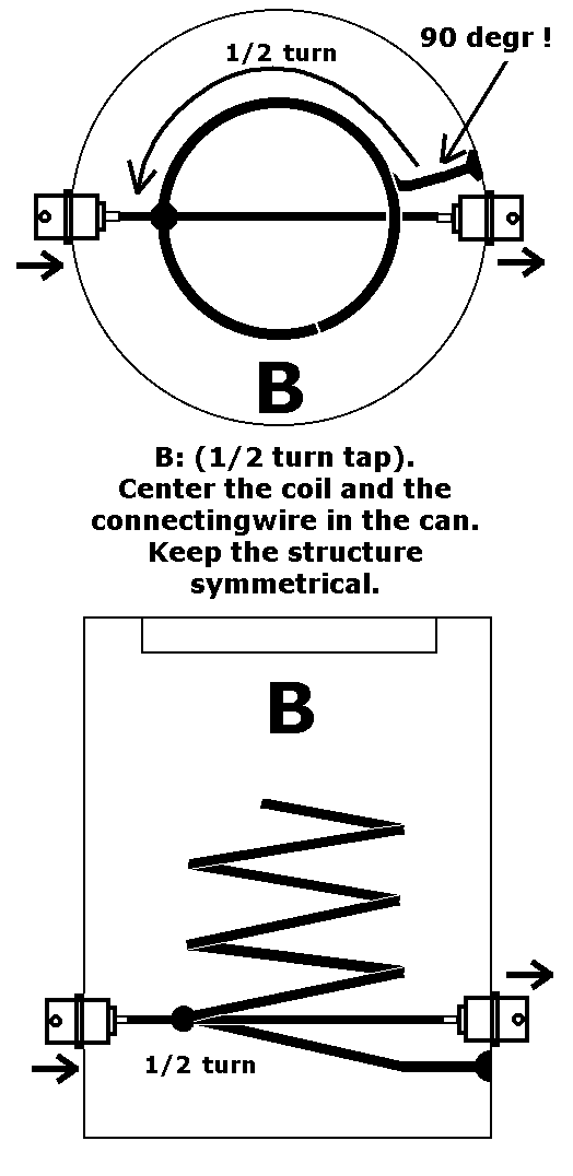
Fig. 2.
|
Adjustment of the shift
(the frequency difference between pass- and notch frequencies).
| - |
Connect the transmission cable between the
measuring equipment to the BNC, using a BNC-T-piece. |
| - |
Measure the notch frequency. It will be much
to low.
Course-tune the notch frequency just below
the wanted frequency. This is done by repeatedly clipping off a short
piece of wire from the free open end of the coil. Tip: 3 mm equals approx.
1 MHz.
Note this "notch frequency".
|
| - |
While measuring the SWR, lower the measuring
frequency, until an SWR of less than 1:1,2 is measured (return loss 15 dB
or so).
Note this "pass frequency".
|
| - |
Calculate the shift = notch frequency - pass
frequency.
For a 155 MHz notch filter it should be 10
MHz.
|
| - |
If necessary, readjust distance between tap
and mass connection, by desoldering and resoldering the coil. Larger
distance means larger shift and vice versa. |
The total number of turns should be between 3.5
and 4.25 .
Fine tuning:
After the shift is adjusted correctly, fine tuning of the notch
frequency can be done.
First, put a bit of solder on the sharp
tip of the coil. It should be round to prevent flash-over.
(See foto 1). By bending the last
two centimeters of the coil in or out, the tuned frequency will become
higher or lower.
If you want, now you can drill a 4 mm
hole in the side of the can, beneath the position of the top of the
coil. Solder a 4mm nut on it. A 4mm screw will act as fine tuning
condenser.
When the lid is placed on the can, the
resonator will lower in frequency. The more "headroom" the
coil has, the less detuning. Always place the lid FIRMLY on the can.
After the filter is tuned correctly,
check the SWR (<= 1:1,2), insertion loss (0,25 dB), and notch
deepness (abt. 38 dB).
|
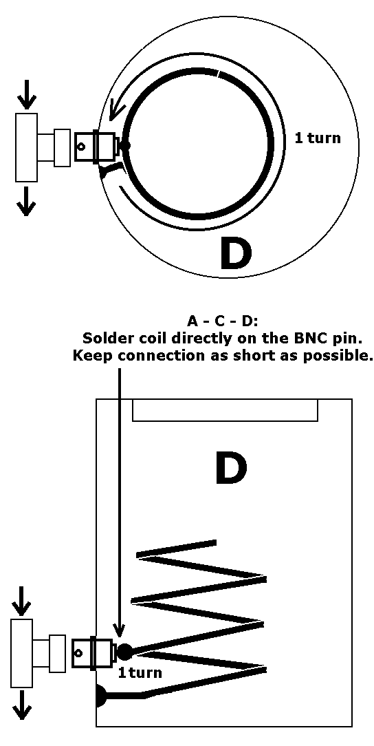
Fig. 4
|
Coil support.
If the filter works satisfactory, you can put a coil support to it. It will make
the construction more stable (foto 1). The support material MUST have
good VHF-properties. The coil-Q can be spoiled by it. I used a thermal glue
cartridge. When molten, it stinks exactly like coaxial cable inner-insulation.
The coil is now mechanically supported, free of
mechanical strain.
| - |
Using a hot knife, cut a piece of
glue cartridge, 5 mm longer than the free space between the coil
and the screening. |
| - |
Using a pair of pliers, position and
hold the glue piece between coil and screening.
Using a small blow torch, carefully heathen the outside of the can
at the position of the support, until the glue melts well.
While holding it still, let it cool down, until the glue color
again looks like milk. |
| - |
Using a hot solder iron, warm the
coil directly beside the support, until the coil has molten itself
into the support.
Let cool down. |
|
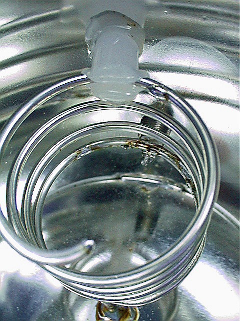
Foto 1.
Observe: as the tap is at 1/2 turn, the shortest mass connection at a
right angle was here to the bottom of the can. Note also the slightly
bended coil-end in order to tune the resonance frequency exactly. |
Fine tuning:
| - |
Press the lid FIRMLY onto the can. Measure
the notch frequency.
Note how much it is lower than the wanted
frequency.
|
| - |
Remove the lid.
Again measure the notch frequency.
Calculate the difference due to closing the lid.
Bend the coil tip. Measure the notch
frequency.
Repeat this, until the notch frequency is
so much "to high", as will be lowered, when closing the lid.
|
| - |
Close the lid firmly. Measure the notch
frequency. It must be within 100 kHz from the wanted notch frequency. |
At last, check the insertion loss at 146 MHz, SWR
and notch depth.