 |
 |
| Fig. 1 | Fig 2. |
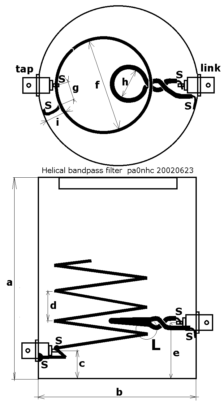
| A single resonator helix bandpass filter for the two meter band. pa0nhc + pa0hpv, 2002 07 08 / 20110307 |
Many amateurs in The Netherlands are bothered by interference of wide data- or broadcast signals, which are caused by strong out of band signals. This article describes the construction and tuning of a single helix band pass filter against these noises.
The tuning of the filter only can be done using measuring equipment by experienced people. This is not a beginners project.
The problem
In The Netherlands above 146 MHz pager networks are active. They locally can produce very strong signals on for instance 154,9875 MHz, 159,990 MHz and 164,350 MHz. On top of that,
these signals are often on the same time active. Modern small VHF transceivers mainly lack of sufficient selectivity in front of the first mixer stage, and do not suppress these
signals enough. The signals can therefore overload the receiver, causing so called IM-products. If the pager frequencies of 154,9875 and 164,350 MHz are active at the same time,
the IM product is 2x154,9875-164,350=145,625 MHz. As this is the mixing product of two FM-modulated signals, and the deviation of one of them multiplied by two, the deviation of
the mixing product is wide, and consequently very loud.
Another IM-product falling into the two meters band is 3x154,9875-2x159,990=144,9825 MHz. The bandwidth of this product can be 80 kHz! These noises can be very irritating because
of their loud, sharply distorted square wave signals.
Local FM-broadcast transmitters can also overload the receiver front stage, thereby generating the second harmonic of the FM-signal, for instance 2x89,5 MHz = 179 MHz. At an IF of 16,9 MHz, this is a mirror-frequency of 145,2 MHz. The broadcast signal will be heard,
loudly distorted, between 145.05 and 135.35 MHz.
The only remedy is: adding extra selectivity.
|
|
| Fig. 1 | Fig 2. |
Possible solutions.
A strong signal outside the two meter band can be attenuated by using a reject filter (notch filter) for that frequency. Using a single helix
filter, 40 dB suppression can be achieved. Other frequencies will less or not be attenuated. This can be of an advantage, if you want to listen to those stations. If more strong
signals must be suppressed, more notch filters must be cascaded. Elsewhere on this site, such filters are described.
Another method is, to suppress all signals outside the two meter band, by applying a band pass filter for 144 - 146 MHz. The possible advantage is, a
better noise free reception of weak stations in the two meter band.
 |
| Fig. 3. |
Below the construction of a single helix band pass filter is described.
If two of these filters are cascaded, the selectivity will be very good, and it probably will be preferable above notchfilters.
The construction of a two-resonator helix band pass filter is described elsewhere on this site.
Which properties determine the quality of a helix band pass filter?
The diameter of the screening, the diameter of the coil, the thickness of the coil wire, and the stray capacitance between the coil and the screening (lid) determine the Q of helix
resonators. The bigger it all is, and the smaller the stray capacitance, the higher the Q, smaller insertion the loss, and better the selectivity will be.
According to data from an ARRL handbook, for maximum unloaded Q of the helix, all dimensions relate to each other. The minimum number of turns is 3. From that, and the resonance frequency, the max. diameter of the screen follows. The coil diameter must be 55% of the screening diameter. The coil height must be 150% of the coil diameter. This gives the winding pitch. The diameter of the wire must be 40% to 60% of the the winding pitch. The total height of the screening must be at least 132% of the screening diameter. For good screening, the top and bottom must be closed, with very good (silver soldered) contact at the bottom.
For 145 MHz the max screen diameter is 12 cm. From that follows: screening height=15,8 cm (or more), helix diameter=6,6 cm, helix height=10cm, pitch=3,3 cm, wire diameter= 13mm to 20mm. Unloaded Q will be 2800.
Cheap and easy to obtain copper screening including top and bottom, of those dimensions, is hard to get, expensive, and difficult to shape. Paint cans and coffee cans are at hand. Copper water pipe is stiff. A coil from those dimensions is difficult to shape. Using copper soft oil pipe or brake pipe should be usable, when filled with fine sand, before bending. Tinned copper wire 3mm dia. is cheap and easy to shape. The here described construction therefore differs from the ideal.
Of great influence on the reached selectivity are: the type (inductive /capacitive), shape (length and shape of connecting wires), tightness of the input- and output couplings, and places of mass-connections. I invested a lot of time experimenting, to reach good results, given the cheap materials used. The pitch was found experimentally. It is possible to get even better results. But it will cost extra money and effort. If you stick to the given dimensions, you can save a lot of time.
Construction.
The design described here therefore differs in some aspects from the ideal properties described above. On top of that, experiments showed, that best results could be obtained
with a shortest possible connection to the helix-tap. The consequence was, that the coil had to be positioned eccentrically into the screening. See fig. 3. Dimensions
"g", "h" and "i" are critical! "S" is a solder-point. "L" is a glue-point.
| Dimension | Height of the can. a |
Diameter of the can. b |
c | Pitch. d |
e | Diameter of the coil. f |
Tap. g |
Diameter of the link. h |
Length of the mass- connection. i |
| (mm) | 115 or more. |
100 | 25 | 11 | 33 | 54 External. |
30 hart BNC-pin to the outside of the mass-connection. |
20 Internal. |
15 External. |
| - | Use a new, clean paint can of 3/4 liters. Drill two holes 9.5 mm dia. for the BNC-receptacles. See "c" and "e". |
| - |
Solder the BNC-receptacles in the holes. Use parts for one-hole installation, with PFTE insulation. |
| - | Wind a 5 turn coil from 3mm tinned copper wire. (Left- or right pitch at choice). |
| - | Bend the mass connection at 90 degr. Clip it to length (dimension "i" is critical!). |
| - | Using a felt pen, make a mark on the coil on the spot where where the solder connection with the BNC-pin must come. |
| - | Temporarily, put a plug on the BNC-receptacles, to keep the pin cool and concentric. |
| - | Tin the coil, BNC-receptacle and can, and solder the coil in place. |
| - | Bend the coupling loop from insulated wire of about 1mm thickness (dimension "h"). Rem: place, dimension and form of the link are critical. |
| - | Twist the ends of the link tightly. This prevents the wires coupling with the coil. |
| - | Strip the insulation of the connections. Bend the connection in a way, the link will fit. Clip excess of wire. See fig.3. |
| - | Solder the link to the pin of the BNC-receptacle, and to the screen, directly against the receptacle. |
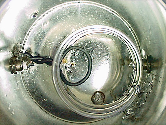 |
| Foto 1. |
The influence of the tap.
If the tap on the coil is to long, the filter flanks will be less steep, and wide band selectivity wil be bad.
If the tap on the coil is to short, the insertion loss will be higher, and good match on both ports, by adjusting the link, cannot be achieved .
In both cases, the coil has to be resoldered into another position so, that the tap has the right length.
The influence of the coupling link.
When the link is to small or to wide, good match can not be achieved. This also is a critical adjustment. In this design the link is made
just a bit to big, in order to make adjustment easy.
Thee link must be positioned between the first and second turn. See to it, that the free space between turns and link is about equal, causing as little as possible parasitic capacitance between them. The link therefore may not touch the coil.
The correct amount of coupling can be adjusted in one of the three following ways:
| - |
Shift the link sideways. The disadvantage is, that the parasitic capacitance between coil and ling will be bigger. |
| - |
Tilt the link. This is more difficult to do and to repeat. |
| - |
See foto 1. Bend the link somewhat oval in shape. |
The last method proved to be stable and easiest. The link remains on the same spot. The whole construction remains symmetrical as possible.
Adjustment.
If a directional coupler is at hand, all measurements can be done using a signal generator with attenuators. The resonance frequency of the coil can be measured with best accuracy,
by measuring the the frequency of max. return-loss, using a directional coupler.
| - | Shorten the top of the coil by clipping small amounts, until it resonates just under the two meter band. Later on, after correctly adjusting the couplings, the coil will be exactly trimmed at the correct frequency. |
| - | Terminate the tap-port with a dummy load 50 ohms. Measure the return loss / SWR of the link-port on the resonance frequency. |
| - | Terminate the link-port with the dummy load 50 ohms. Measure the return loss / SWR of the tap-port on the resonance frequency. |
| - | The return loss on both ports should be over 20 dB on the same frequency, or the SWR should be 1:1.1 or better. |
| - | If the match is not ok, readjust the coupling link, and measure both ports again. |
| - |
If a good match is not possible on both ports at the same frequency at the same time, the length of the tap is to short. The coil has to be repositioned in such a way, that the tap is a bit longer. This is critical! |
| - |
When the match on both ports at the same frequency is OK, then: |
| - |
Measure the insertion loss. It should be less than 0.5 dB. |
| - |
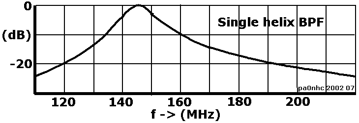
Measure the selectivity. On 120 MHz and 190 MHz it should be -20 dB. |
| - |
Repeat measurements and adjustments until return loss / SWR, insertion loss, and selectivity meet the demands. |
Supporting the coil.
When return loss / SWR, insertion loss, and selectivity meet the demands, the coil can be made more stable by supporting it to the screening.
| - | measure the distance between the coil and the screening. |
| - | Using a hot knife, cut a length of thermal glue 5 mm longer then the measured free space. |
| - | Hold the support between coil and screening using pliers. |
| - | Using a small blowtorch, heathen carefully the outside of the screening near the position of the support, until it melts. |
| - |
keep the support still in place, until it cooled down. |
| - | Using a hot soldering iron, heathen the coil right next to the support, until the coil has molten itself into the support. let cool
down.
The coil is now firm in position, without any mechanical strain. |
| - | Secure the coupling link into place, using a glue pistol. See fig.3 point "L". See to it, that the glue has attached itself. |
| - | Check the return loss on both ports. |
Fine adjustment.
The resonance frequency of the coil can be measured with best accuracy, by measuring the the frequency of max. return-loss, using a
directional coupler.
| - | Determine the resonance frequency without the lid. |
| - | Determine the resonance frequency with the lid on the can. |
| - | calculate the frequency difference caused by placing the lid. |
| - | Remove the lid. Tune the coil by clipping small pieces of wire from the top of the coil. Measure the resonance frequency carefully. It should become just as much to high, as it will be lowered by replacing the lid. |
| - | Now first put a drop of solder on the sharp coil-end. This can prevent arcing due to the high voltages when transmitting with high power. |
| - | Measure the resonance frequency with lid. Fine adjustment can be done, by bending the last 1 or 2 cm of the top of the coil a few millimeters in (higher frequency) or out (lower frequency). Try to get a resonance frequency within 100 kHz. |
| - | At last, check return loss / SWR, insertion loss, and selectivity. |
You could drill a hole near the position of the coil-tip, and solder a M4 nut on it. A M4 bolt then serves as a fine-tuning condenser.
73's, Nico, pa0nhc.