A power tap retrieves a weak sample
of the output of an RF power amplifier. The for the transmitter
used software compares the transmitter output spectrum with the power
amplifier output spectrum, and eliminates the differences in both
spectra. The distortion generated by the power amplifier is then
eliminated.
A purer amplifier power output is the result. The amplifier
output spectrum is then (nearly) equal to the driving transmitter output
spectrum.
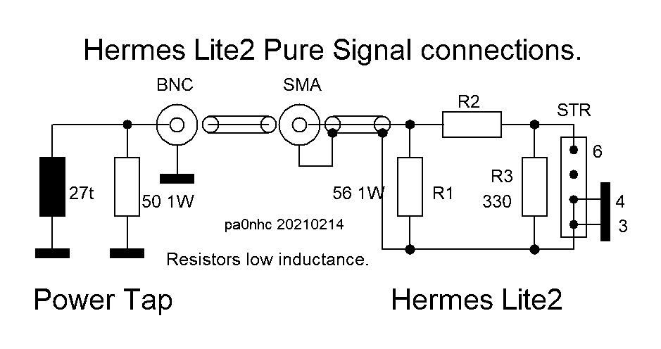
The attenuation by this Power Tap is
nearly 35dB (3000x less power, 1/2W @ 1.5 kW). The output is loaded with an internal
50 Ohm load, plus an external 50 Ohms (attenuator) network.
My Power Tap does not contain an internal
attenuator. The attenuator is placed inside the HL2 housing, ensuring a relative high value of RF voltage
sample on the connecting coax cable between power tap and HL2, ensuring the
best interference insensitivity. And it ensures good match at both ends
of the connecting coax. Resulting also in high and very constant output voltage at the end of the connecting coax
(+/- 0.3 dB @ 0.2MHz - 50 MHz), and the best possible Pure Signal
correction.
|
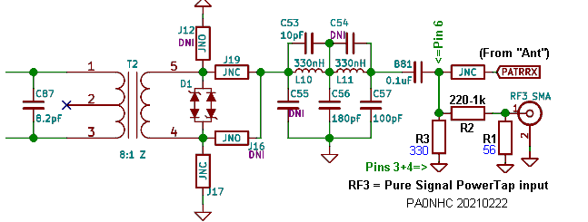
As the Power Tap output (1.3Vrms @
100W and 5Vrms @ 1600W) will mostly be to strong, an attenuator is needed in
(or at)
the TRX pure signal input. See the attenuator table and the
modification for a Hermes Lite2 at the bottom of this page. Cheap BNC plugs sometimes have bad
contact resistances between grounding contacts. To achieve minimal common mode
current problems, best use only high
quality (SMA) plugs and jacks with high temperature resistive PTFE
insulation,and good (double screened)
coax (RG316) .I recommend a box
with small width / height
dimensions,
to keep
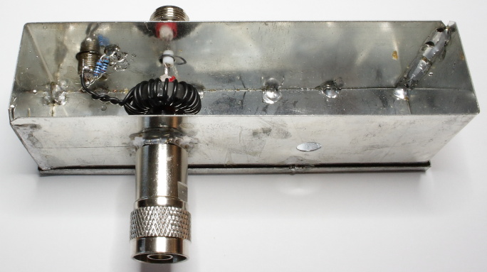
internal RF return path lengths of the main power circuit as short as possible. I
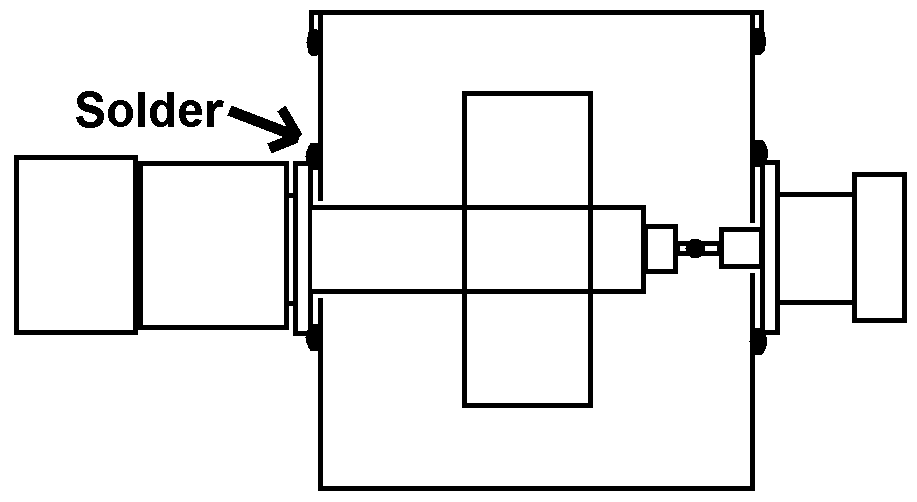
used a tinned steel box as housing for the power tap, in order to be able to solder the connectors
onto the outside of it. Solder all seems at the inside of the box, at
about 2cm intervals. Use a 120W solder iron at
400C. As the closing lid cannot be soldered
at the inside, be sure that the solder flows there in-between the box outer
surface and the inner surface of the lid. See sketch. A
small aluminum die cast box could also be used. Be then sure, that the grounded
parts of the N- , BNC or SMA connectors make good electrical contact
only
with the outside of the box. Tap thread
into the box
for the busses fixing screws to achieve good ground contact. |
Construction in a tin plated steel sheet box.
Drilling holes.
The hole diameter for the receptacles depends on
the connector version.
The hole diameter for the (left hand) N-male plug :
The diameter of the hole in the box =
the diameter of the hole in the inside
of the N-connecor nut (about 11 mm).
The
hole
diameter for the (right hand) N-female receptacle :
The diameter of the hole in the box =
the diameter of the PTFE insulation in the flange
(about 11 mm).
The
hole
diameter for the BNC-female receptacle is about 10 mm.
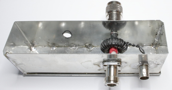
The coil :
The coil is a current transformer. More turns = less output
current (and less RFvoltage over the totally 25 Ohms load).
Wind 1.2mm outer dia. insulated hookup wire 27
times through the ferrite core hole. Wind all turns side-by-side, in one layer, on a FairRite
OrderNr. 5961000601
core, or Amidon FT82-61 ring core.
As the coil is a current TRANSFORMER, only use mix #61 ferrite.
as this type of ferrite material has the optimal transformer properties up to 25 MHz.
The output load resistor is 50 Ohms. For powers up
to 2.5 kW, a 1W low inductance resistor should do.
Or use 2x100 Ohms 1/2W low
inductance in parallel, or 2x 56 + 2x47 ohms 1/4
W low inductance in parallel.
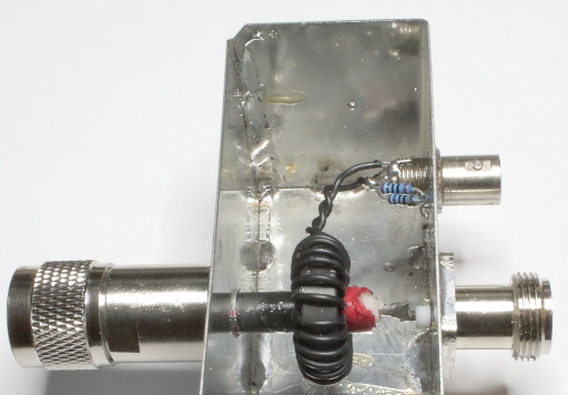
TWIST both coil ends firmly.
Solder both wire
ends DIRECTLY onto the BNC inside end. Solder one wire to its center pin, and the
other wire to the outer rim (grounding, see photo).
If the phase of the output signal needs to
be changed,
then exchange the solder points of both wires the BNC.
|
|
|
The coil is MAGNETICALLY
coupled
with the CENTER
conductor of
the coax, by means of the only suitable ferreite material for the
frequency range up to 30 MHz..
The coax screening is insulated at its end.
NO
RF current runs
therefore inside the coax screening. The piece of coax screening solely functions as a static screen
between the the coupling coil and the current carrying coax center.
The screening of the coax is only at its
beginning connected ("grounded") to the inside of the
male power input plug. NOT to the box. See photo and sketch below.
|
 |
The RF current in the
main power channel flows (at the center conductor), from the power tap
input connector to the power tap output connector.
As the screen of the coax is
interrupted at the inside of the power tap box, the
return current from power tap output to input can run inside the
box only back through the internal-surface of the box.
The box width + hight therefore will lengthen the internal return path,
and can be of influence to the power tap properties.
To keep the return-path-length at the inside
surface of the box short, a small box with small width and
hight is preferred.
|
 |
|
Installing the
plugs, coax and coil:
Use good quality connectors with PTFE
insulation. Put a plug on the soldered receptacle to keep the center
pin/bus centered.
1. Solder the nut of the N-male
plug to the outside of the box, centered to its hole in the box.
Solder the N-female receptacle to the outside of the
box, with its flange centered to
its hole in the box. Solder the BNC-female receptacle to the outside of the
box.
2. Pre-install a (RG214) coax piece into the remaining plug
body of the N-male, and roughly cut it to the width of the box.
3. Shift this coax piece through the hole in the box, then temporarily tighten
the plug, and cut the coax at exact length.
4. Then unscrew the plug.
5. a. Remove 5mm at the end of its screening.
b. Remove 3mm at the end of its inner insulation.
6. Shift the coax piece through the hole in the box,
and shift the ferrite coil over the coax.
If the coil fits to loosely over the coax, then wind some insulation tape
over the coax, until the coil fits snugly and centered over the coax.
7. FIRMLY tighten the N-plug body onto its soldered nut. It may
not loosen during later usage.
8. Solder the coax center wire to the pin of the female N-bus.
REM :This end of the coax screening must nowhere be connected.
9. Twist the coil ends, trim them and solder them directly to the BNC pin and
ground surface
(see photos).
11. After testing, fix the coil to the coax with glue, to prevent changes
of performance.
12. Solder the lid.
|
 |
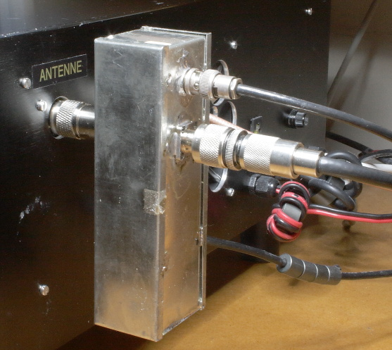
| The completed "Power Tap" is here connected to the
antenna (output) bus of my PA.
As no RF radiation problems existed caused by common mode
currents, no Common Mode Chokes needed to be installed over the coaxes.
|
 |
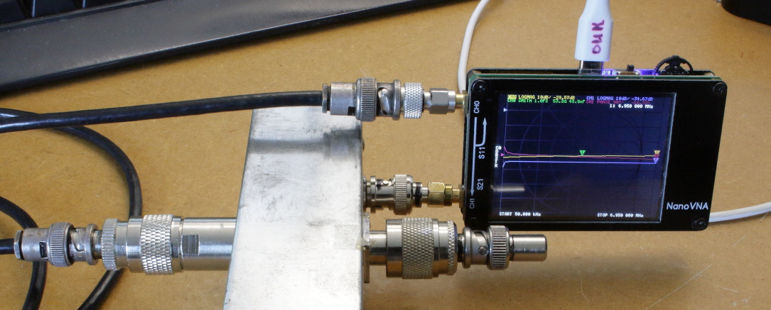
| Power tap measuring setup.
The (Nano) VNA was first calibrated including 1.5m
RG58 cable.
REM : Y-scale ranges below are sometimes very small. Frequency characteristics
are very flat.
|
|
|
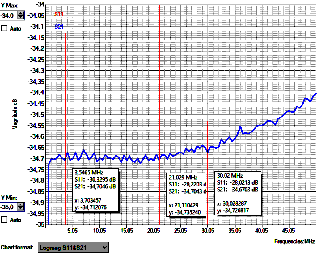
Results < 50MHz :
Coupling Main to BNC-out.
REM : ZOOMED, only
1dB Y-scale range !
Flat response :
0.2 - 50 MHz : -34.7 +/- 0.3 dB.
Ref = 21MHz :
30 MHz : + 0.034 dB.
50 MHz : + 0.304 dB.
|
 |
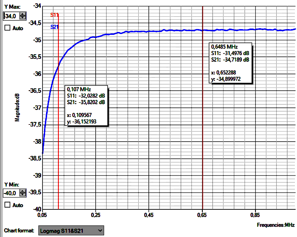
Response < 1MHz Main to BNC-out
(Ref = 21MHz )
Y-scale range :
6dB.
REM : Below 100 kHz characteristic of the NanoVNA
itself also falls.
0.20 MHz : - 0.304 dB.
0.65 MHz : + 0,015 dB.
|
 |
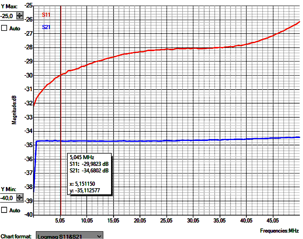
Red : Main channel
return loss.
Blue : BNC-output.
Y-scale range 15dB. |
 |
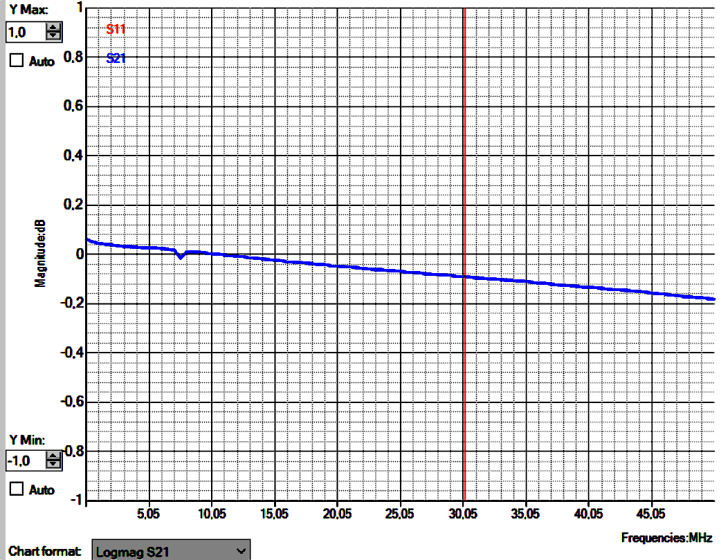
Main channel loss.
Max 0.25 dB including 1.5m RG58.
REM : ZOOMED-IN, only
2 dB Y-scale range !
|
 |
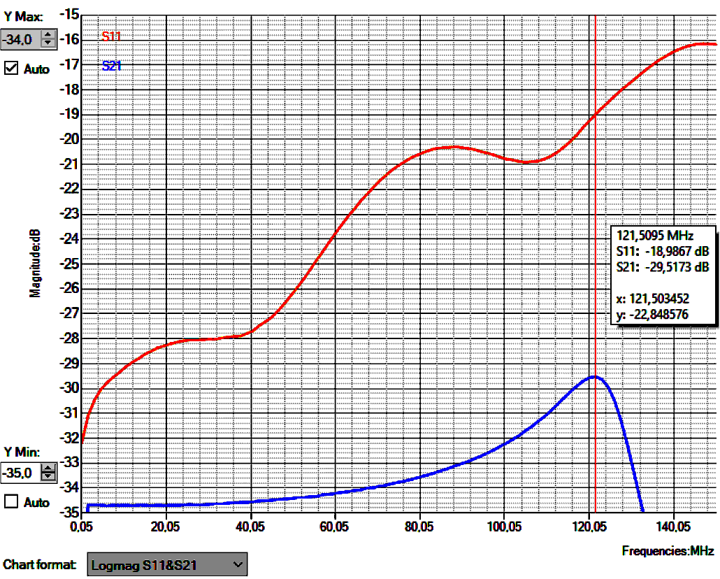
Blue : BNC-out
coupling showing the
VHF resonance in the coupling coil at 121.5 MHz.
Useable output frequency range :
100kHz - 75 MHz +/- 1dB.
Red : Return
loss of the main
channel with 1.5 m RG58 coax connected.
|
 |
|