|
|
|
| << |
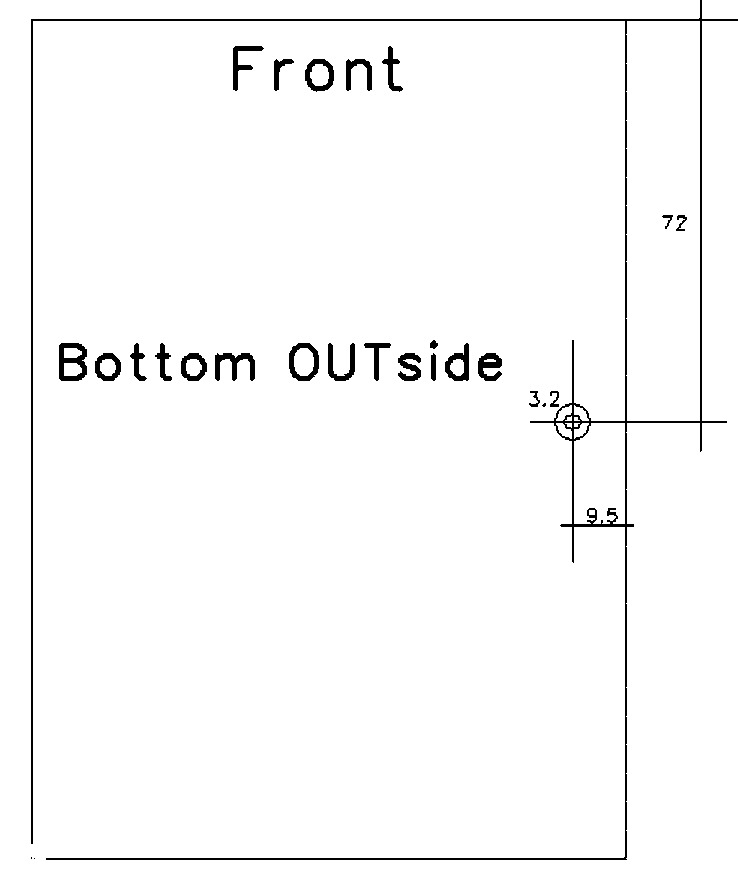
Alternative heath
conductor and
drill plan. |
With this aluminum heat conductor fitted, the PCB
sits without mechanical stress flush with the side of the cabinet.
Fist remove on the thermal contact places of the box the black layer. The
thermal block should be installed (like shown on the HL2 internet site) with
some heat compound inserted into the slit in the side of the box, onto the
bottom contact surface of the box, onto the thermal contact surface of the HL2
board, and at all thermal contact surfaces for the conductor.
I installed a 30mm small fan in the lid, right above the power FETs. It is connected to the +12V supply with a series resistor of 270 Ohm 1/2W, and then runs silently on low speed. The series resistor should allow that the fan just starts running positively.
Insuring best cooling.
|
|
|