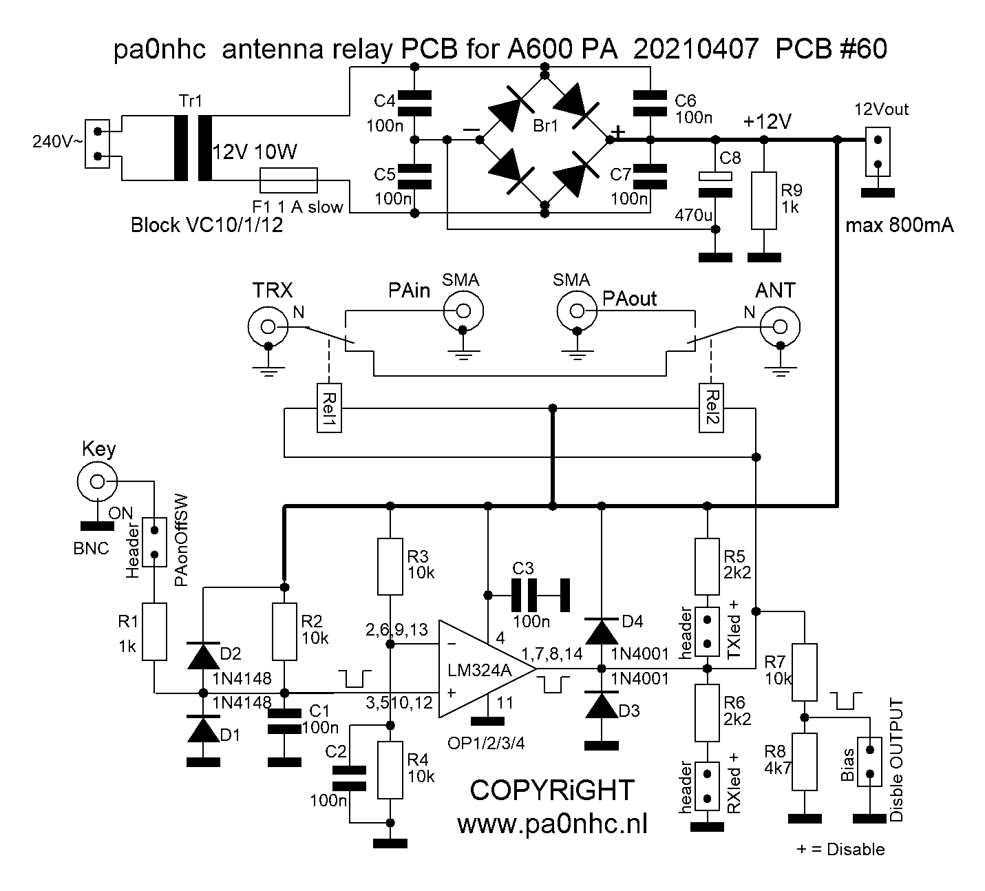
Printable enhanced scan of A600 schematic.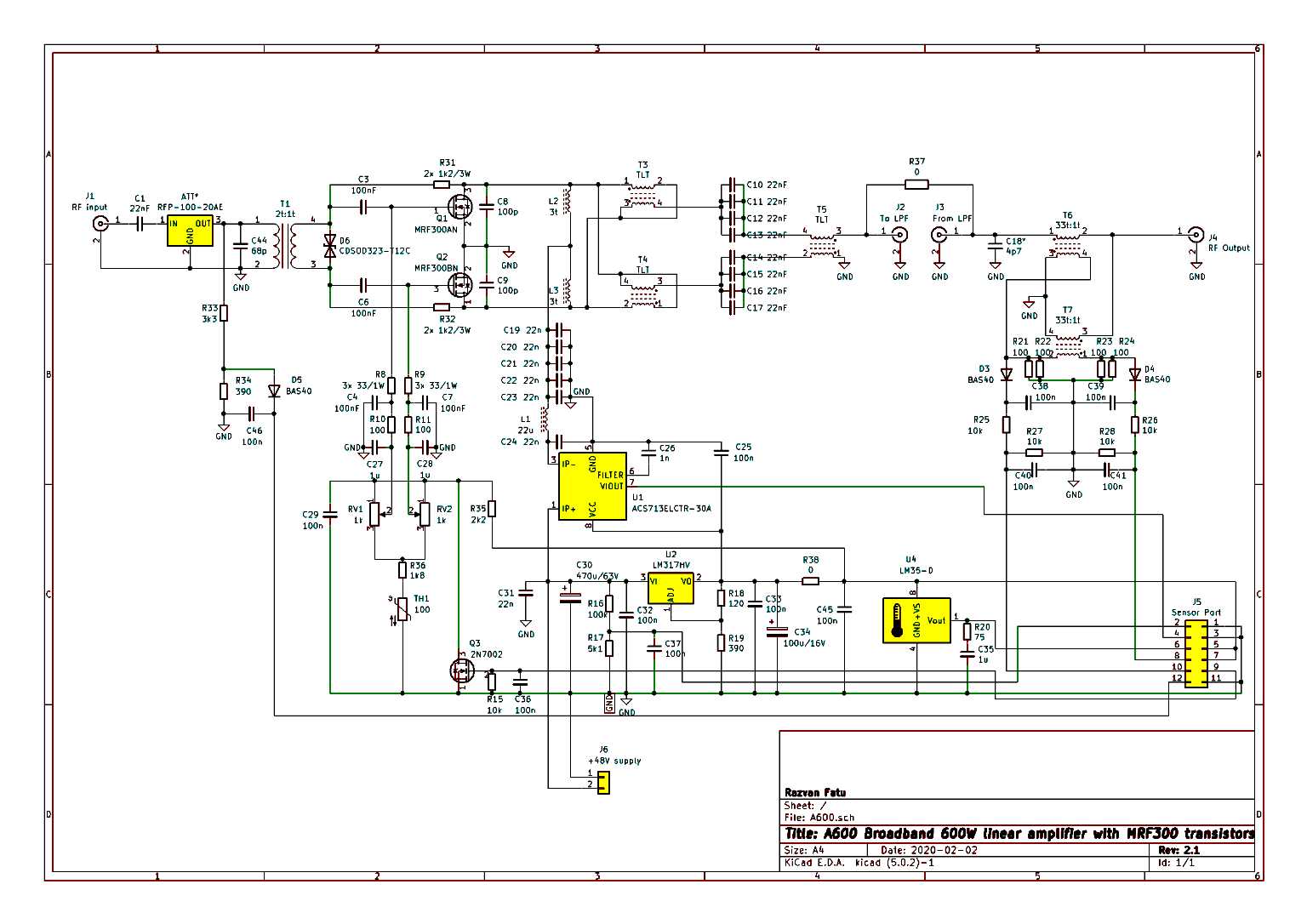 |
Some PA0NHC A600 modifications (see descriptions for more).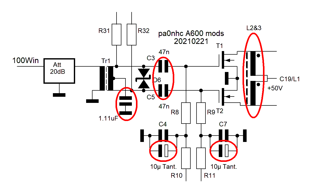 |
New PEAK meter
schematic for 6 identical circuits on one board.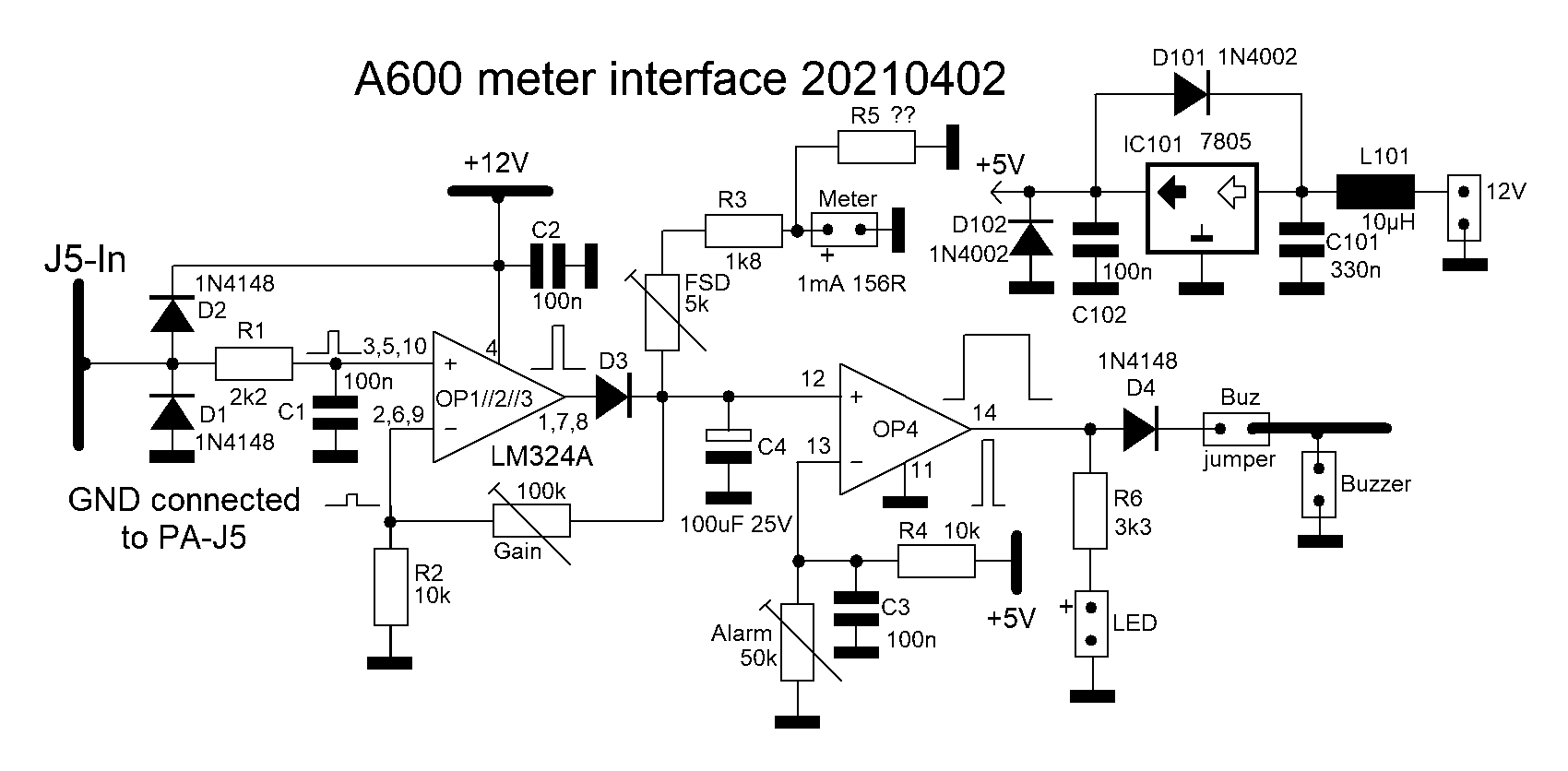 All six circuits are identical. The PCB is available. In circuit4 (FET drive) is one extra resistor parallel to signal input line J5-12 installed : R47 = 22k. It compensates meter drift due to LM324A input leakage current. |
Peak meter
circuit1 parts locations.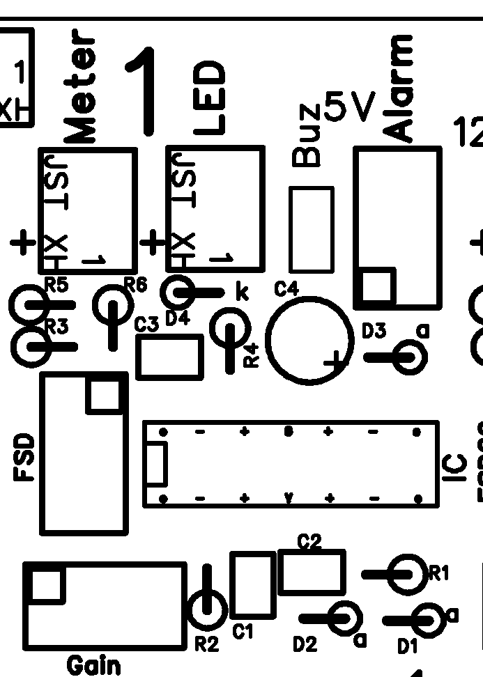 This picture shows the part locations only for meter circuit1. The parts locations for circuits 2 to 6 are the same. While part designators for circuit2 to circuit6 are numbered 20 to 60 higher. Example for circuit3 : R31, C31, IC31, Meter31, Gain31 etc. |
| Band switch schematic. Output to LPF is TTL level. Top and bottom copper surfaces are insulated from cabinet ground. Power and ground connected to LPF through 10 wide flat cable. 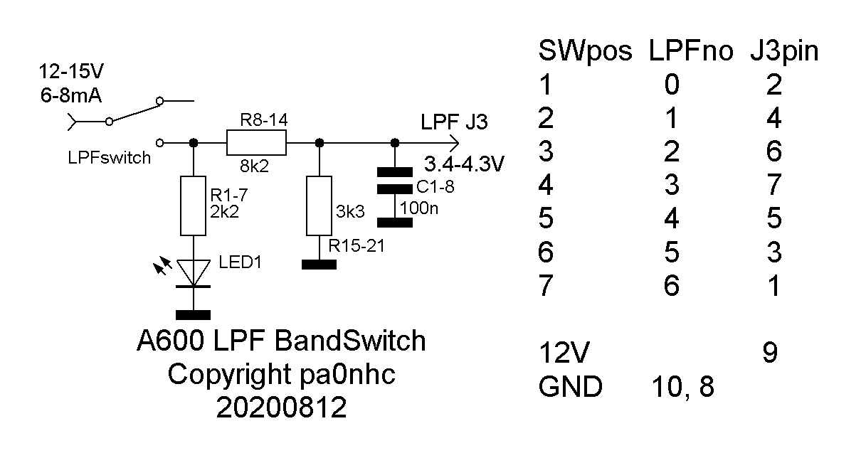 This PCB is available. |
|
Back panel
schematic. |
|
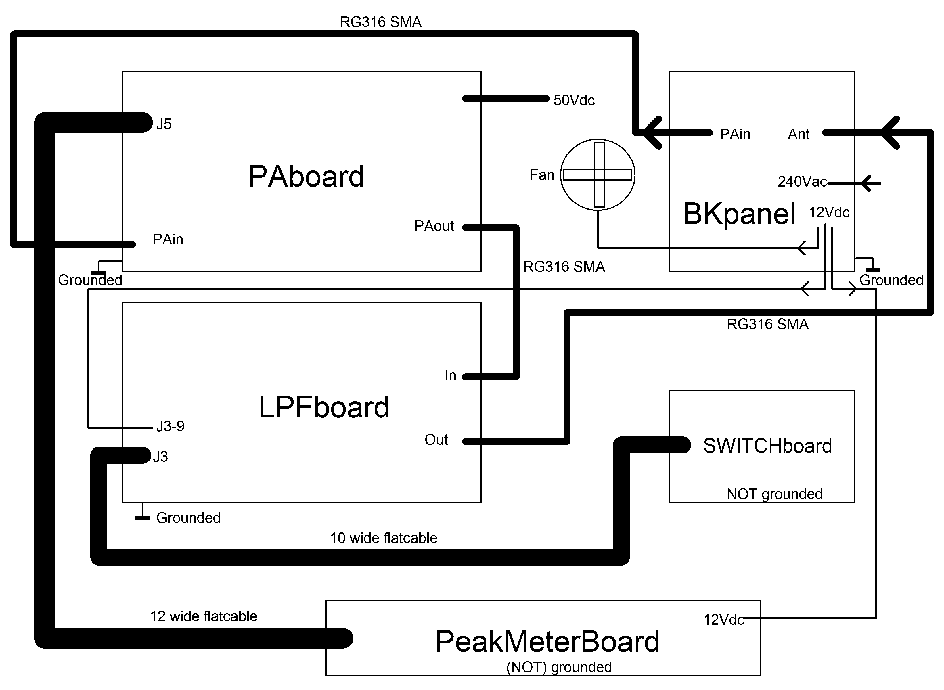
pa0nhc A600 PA block/cabling diagram. |