|
|
|
| << |
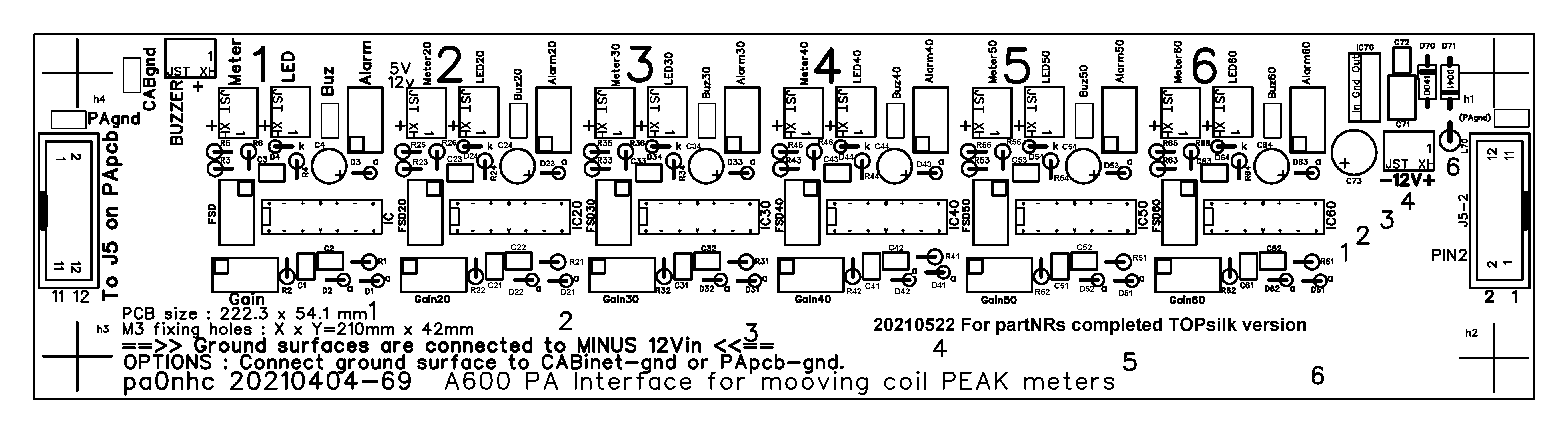
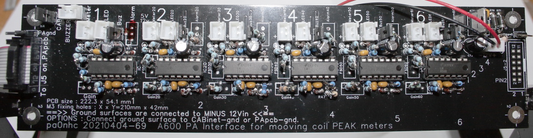
A600 PA peak
reading meter PCB. |
. . . to reload the latest updated page from the Internet Server.
One PCB for six peak reading
moving coil meter interfaces.
Read
all info carefully before installing components into the PCB.
20210523-41
Meter PCB adjusted components value table.
With the here recommended fixed value
resistor combinations, calibrated meter indications are achieved for 1mA moving coil
meters.
Six
20210505
85C1
1200DPI moving coil meter scales PDF.
Print in color on A4, in high quality, and picture scale 100%
PDF TOP silk with updated component numbering 20210522.
Drive.
The new drive meter range is 5Wp, and its alarm level is 4Wp.
My modified PA needs around 1Wp input for 400Wp output.
GATE DRIVE
VOLTAGES of 16Vpp (about 4W input) or higher can blow the FET gates !
The
safest drive method :
Always use the max. output from the transmitter (me : Hermes Lite2 4W).
Use an internal attenuator (here 6dB) inside the PA, which is connected between the PA back
panel and the input of the PA PCB.
Lower the PA drive with it to what is needed for 400Wp output (here 1W).
Circuits test and calibration with DC input test voltages.
The most easy way to assemble and
achieve calibrated metering circuits, with still the possibility to correct
meter readings for small signaling differences, is installing pre-adjusted
trimpots. You should pre-adjust thes "GAIN" and
"ALARM" and "FSD" trimmers, BEFORE inserting them into the PCB. See for the NOMINAL values in columns "GAINx" and "ALARMx" in
the PDF table. FSD40
is a resistor of 270 Ohms. All other FSD resistors are 3k035.
| PCB circuit |
Component |
Indicates | J5 input pin |
| 1 | --- | 50V supply | 2 |
| 2 | 20 | I supply | 4 |
| 3 | 30 | PCB temp | 6 |
| 4 | 40 | Reflected | 8 |
| 5 | 50 | Forward | 10 |
| 6 | 60 | Drive | 12 |
| Power | 70 |
After finishing the PCB :
Connect all meters and LEDs.
Place jumper PAgnd.
The PCB is now temporarily connected to the PA cabinet.
Temporarily set a CABgnd jumper on the PCB to connect the meter
PCB to CABgnd.
Then disconnect the flat cable from meter PCB J5.
REM "x" is the PCB part
number prefix.
In circuit 1 "x" is empty.
In circuit 2 to 6 "x" is 20 to
60.
Example : In circuit4 is D5 numbered as (Dx5)
or D45.
REM : all meter circuits 1-5 (when having no input connected) will show burning LEDS. This is normal.
1. Connect a (low impedance) test voltage source (5Vdc max. "+"
to the appropriate input pin at J5,
and "-" cabinet ground).
2. Connect the 12Vdc power (max 18Vdc).
3. Set the test voltage to full meter
scale deflection (see metering table).
4. Connect a digital DC voltage meter to Dx5
k (cathode).
5. The voltage should be 5.0Vdc (adjust with "GAINx").
PCBcircuit4 (reflected power) should indicate 2.23Vdc.
6. Check the moving coil full meter deflection (adjust with "FSDx").
7. Set the input voltage to the alarm level (see metering table).
8. The alarm LED should just light-up (adjust "Alarmx").
Together wit a burning LED, a
buzzer can sound.
Go on with the next meter circuit.
Measure the PCB temperature with an infrared
thermometer and compare it with the meter indication.
When the calibration is finished, remove the
jumper "CABgnd", and re-connect the flat cable between meter PCB and
PA PCB. The "PAgnd" jumper should be placed.
To prevent a ground loop, only the "+" of the 12V supply should be
connected to the metering PCB. The 12V "-" should not be connected but
is connected to the PA PCB with the J5 flat cable.
After connecting the PCB with the
meters and with the PA in mode standby :
a. adjust the mechanical zero screw of the power current meter for zero
indication.
b. adjust the mechanical zero screw of the PCB temperature meter to the
actual room temperature.
Transmit a 300W carrier until the moving coil meter
indicates 50C. Compare with the PCB temperature near Q1 (MRF500AN) measuring it
with an infra red meter.
|
|
|
|
Why peak meters.
Power Amplifier units not only can be damaged
by continues overdrive, but also by very short peaks.
To indicate dangerous levels, PEAK powers / voltages / currents indicators
should be used, not mean value indicators.
The amplifier circuits on this PCB have
therefore fast attacks, and slow decays.
Speech and continues tones should give (with equal drive) about the same
meter indications.
This single PCB allows reliable connections with JST XH plugs to six moving coil meters, LEDs, buzzer and 12Vdc power. Placing nine jumpers to allow a buzzer to sound, and to choose grounding location. The six meter buffer circuits 1 to 6 are identical, with some identical component values. All to be connected moving coil meters are cheap 1mA 85C1 type (Aliexpress). This PCB is connected with only one 12 wide flat cable to the 2x6 pin signal output bus J5 at the PA PCB, and to a +12V supply. Meter indication and alarm levels are adjustable by trim pots, or readily calibrated by installing recommended resistor combinations.
Please excuse me : Due to a software problem in the
by me used old FREEPCB design software, not all component references are printed on
the PCB.
But identifying components is
easy : When i added a new circuit copy of circuit1, all references were simply updated by adding
10 more to the references of the added circuit.
Examples :
All lowest component references in circuit1 are numbered starting at "
1"
( R1, C1 etc.).
All lowest component references
in circuit2 are numbered starting at "21" (R21, C21 etc.).
All lowest component references in circuit3 are numbered starting at "31"
(R31, C31 etc.).
and so on.
The 5Vdc circuit component references are numbered starting at 70.
See the picture above.
Except the trimmers, most components with the same last reference cyfer in circuits 1 to 6 have the same values.
Ordering components.
The column "Remarks" in the parts list gives some indications
where components are available.
Conrad orderNrs are given as reference for
component properties. You can
order at Conrad.com (only in EU, order for more than 50
Euro for free postage).
Or order equivalent components elsewhere. Then look
at Conrad.com what the exact
component properties are.
Installing components.
Download the PDF TOPsilk. At the PCB missing component
numbering is completed on the PDF. Print it when installing components.
This component soldering is time consuming and focused work. More than
130 parts must be installed.
Not everyone can handle 1x2mm or smaller SMD components. Al components are
therefore wired.
To save space, nearly all components are placed vertically. All resistors are 1/4W metal
film 1% or better.
Connect the solder iron tip electrically to the mass surfaces of the PCB to
prevent static damages. Handle the ICs with care.
Pay attention to the :
- Correct "trimmer" holes, if fixed resistors are installed in
stead of trimmers. Three of the four holes are interconnected.
- Polarity of diodes. Stripe on the diode body = cathode,
on the PCB marked as "k". Diode anode is on the PCB marked as "a".
- Polarity of electrolytic capacitors. The longest wire
is + (positive).
- The notch at IC sockets, at the PCB, and at the ICs (pin1).
The downloadable PDF table and PDF list give values for replacing the trimmers by fixed resistors.
Afterwards
fault search is time consuming.
To
prevent placement faults and malfunction, i suggest to work as follows :
First place and solder components
all of one same value.
Example : Place solder all 2k2 resistors R1, R21, R31, R41, R51, R61.
CHECK your solder work !
After that, place components of one other same value.
Example : Place and solder all 10k resistors R2, R22, R32, R42, R52,
R6.
Solder component types in the following order:
- IC sockets. See the notch at one small socket
side and on the PCB.
- Ceramic capacitors.
- Diodes (See "k" = cathode, the side with the ring on it,
"a" = anode).
- Resistors. R47 is not installed.
=> In the drive power circuit
a 22k
resistor (R67, not printed at the PCB) must be soldered parallel at its input
(at the PCB bottom parallel to D61).
Before soldering
fixed resistor pairs in stead of trimmers GAIN, FSD and ALARM :
MEASURE the total value of the
pair with a digital ohmmeter. It must be within 1% of the nominal value in the metering table.
FSD40
is a resistor of 270 Ohms. All other FSD resistors are 3k035.
- Jumper pins.
- JST XH busses.
- Trimpots. You should pre-adjust the trimmers
to nominal values, BEFORE inserting them into the PCB. See PDF
table.
- Elcos. 6mm elcos JUST fit between other
components. Do not use thicker types.
- IC70.
- Insert the ICs. See the notch at one small side.
Handle the ICs with anti-static care.