Last update: 000114. Step by step assembly:
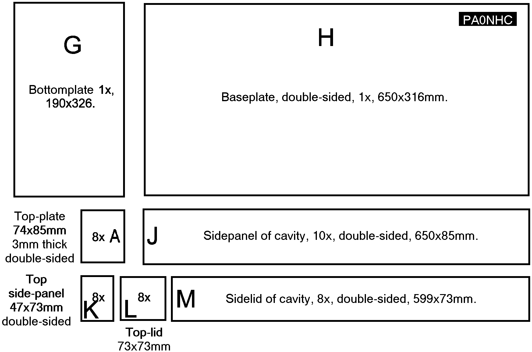
There are files with separate drawings of all all copperclad parts. You can save each drawing, and print it with a drawing program separately in good quality.
1. Cut all pieces of copperclad, and drill all holes.
Cutting should best be done on a special cutting bench, which allows all dimensions and angles to be accurate. Cut all parts with same dimensions in one go, NOT readjusting the dimension. This way all same dimensions are really the same. It saves a lot of work afterwards, and make aligning parts easier. Raw sides should be smoothed a littler using a fine file.
Be aware of the fact, that some sides need to be filed so, that one coppersurface cannot make contact with other coppersurfaces.
The 22mm holes in top-plate "A" can first be drilled at a smaller size, f.i. 13 mm.
Then widen the hole with a pointed grinding-stone in a table-drilling machine. Widen the hole until the diameter of the hole in the coppersurface is equal to the outer diameter of the central conductor.
Then drill the other side of the hole in "A" to the same diameter. Turn plate "A" around, and slowly widen the hole alternately on both sides until the 22mm-pipe just fits in the hole.
Do not widen to much, as this makes soldering "A" to the central conductor "B" more difficult.
You could also file the last piece of the fiberglass in the hole, so the plate fits tight, with the coppersurfaces nearly in contact with the pipe.
Widen the holes for links "C" until the link just fits.
Remove with a 4.5mm drill the copper layer at both sides of the holes near the big 22mm hole (insulation for the "hot" side of the link). Warning: the TOPside of the other link-hole may NOT be widened. At that place the mass-side of the link must be soldered to mass-suface (see drawing).
Finish the sidelids "M", by filing the edges on the inside surface at 45 degr, to prevent contact between the cavity sidewalls, and the inside-surface of the sidelid.
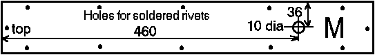
Only the outer surface can later be soldered to the sidewalls!
Drill 12 small holes at 5mm distance from the edges in each lid.
Solder rivets or pieces of thick wire in the holes to both copper surfaces. The inner surface becomes connected to the outer surface only through those wires.
Drill and tap M6 in bushings "D".
Assemble the finetuning-bolts in them.
Solder the assembled bushings "D" on the outside of the sidelids "M".
File all edges of the toplids "L" at 45 degr. to prevent contact with the sidewalls.
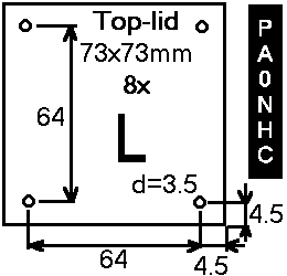
Clean and spray with transparent paint.
2. With a pipecutter, cut all central conductors from 22mm pipe. The sharp rim wich the cutter leaves on the inside of the pipe is heplfull for making good contact to the plunger.
Saw the slits at the bottom ends with a thick sawblade.
Smoothen the rims at the inside
only at the top end of "B" (not at the end with the slits).
The sharp rim at the end with the slits enhances contactpressiure between the
plunger and the central conductor! Leave it that way.
3. Cut the tuning-rods.
4. Cut 7 pieces 1/4 electrical wavelength long 50 ohms double
screened 2.5mm PTFE coax .
Cut 1 piece 50 ohms PTFE coax 1/2 electrical wavelength long.
The measured length is the length of the inner insulation without the length of the pieces inner conductor which have to be soldered later. Measure with the coax streched into a straight line.
When cutting the inner insulation, the knife may not touch the inner conductor of the coax! This earlier or later couses breaking of the inner conductor. Just make an insision, and gently turn around the insulation untilt it comes loose. Practice this first. PTFE is less easy to cut, and cannot be melted. Do not use automatic cable stripper.
Keep the unsheelded part of the inner insulation of the coax as short as possible (max one mm) ! The inner insulation must later fit directly to the soldered connection.
NO pictails are used for connection of the screening to mass. Just cut off the screening onto the inner insulation.
Tin-solder the ends of the screening and the tip of the inner conductor.
Remove the outer insulation of the PTFE coax to allow soldering the braid to mass later.
Coaxlength:
Be sure, to use the correct velocityfactor for the actual coax used! PTFE has other properties than normal coax!
Calculate the cable-lengths to the NOTCH-frequency of the cavity where the cable will be connected to. Calculation: mechanical length = velocityfactor X fre air wavelength.
Especially the 1/4 and 1/2 wave cablepieces connected to the antenna-outlet are
critical. They act as a frequency-dependent switch. After connecting the Rx-part and Tx-part of the filter together, the separation of the RX and TX filterparts, and the
total deepness of the notches depend on the correct lenghts.
Due to the severe mismatch on the notchfrequency, the 1/4 wave pieces between the cavities act as impedance transformers, decoupling here the interconnected cavities at their notch-frequency, avoiding mutual influencing,
but coupling them on the pass frequency.
On the pass-frequency, the cavities are matched to the cables. The cables then have no influence, and due to the short length, very little loss.