 17. Cn
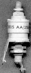
Use for Cn a stable, low loss, low self-inductance trimmer with fine-tuning capabilities. A max. value of abt. 10 pF should be enough.
16. Adding a notch-C to a cavity (shift: -600kHz).
Signal generator and detector:
16.1 Use a transmitter of the synthesizer-type with tuningsteps of 2.5 kHz as signal generator . A counter is then not
nessacery.
16.2 Connect a VSWR-meter to the beginning of the 1/2 wave input-testcable. This to enable to check for correct tuning of the filter to the passfrequency (low VSWR).
16.3 For measuring the notch, a sensitive detector is needed. Use f.i. a Skottky diode+feedthrough-C, mounted in a plug on a T-piece, terminated with a dummyload.
16.4 If you are lucky to have a spectrumscope or -analyser, reading is easy. Connect them through a 20dB power-damping-pad to the end of the output-cable.
17. Cn
Use for Cn a stable, low loss, low self-inductance trimmer with fine-tuning capabilities. A max. value of abt. 10 pF should be enough.
On a surplus-market i found concentrical laboratory-quality air-trimmers from Philips with fine tuning-thread. They are ideal.
17.1 Do NOT use wire for connecting the trimmer-C's to the links. Use abt. 10mm wide copper strip. It has a lower impedance, resulting in a deeper notch!
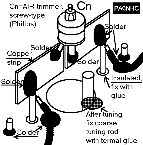 17.1.1 Solder the notch-C to the strips.
17.1.2 Solder the strips to the hot sides of the links. Keep the strips as near as possible to the topplate "A". The (test-)cables will be soldered to the link-side of the strips at the links.
17.1.3 Check that the tuning-rod cannot touch anything, and nothing touches the toplid when the toplid is in place.
17.1.4 Connect the 1/2 wave testcables to the LINKwires, at the center-line of the 10mm strips. Solder to the LINK, not to the strip itself. Do not use to much solder. This enables lateron to solder the 1/4 wave PTFE cables at the exact same point. This to ensure that the shift is not altered, when connecting the adjusted cavities together.
17.2 While measuring/adjusting the shift in a notch-cavity, the cavity must be tuned to min. VSWR at the pass-frequency, and not to min. insertionloss. The reasons are:
17.2.1 For stable operation of the transmitter and the receiver, the filter-VSWR must be low at the pass-frequency.
17.2.2 At this type of notchfilter (ARRL), min. VSWR does NOT coďncide with min. insertion loss. The difference is abt. 50 kHz and a fraction of a dB.
I think that this is the reason, why this type of notch-cavity has a insertionloss of abt. 1dB per cavity, while other types can have less insertionloss per cavity.
17.2.3 When the filter is in service, a quick check for correct tuning of the filter can be done, by comparing VSWR and insertionloss to the ones, when the filter was last adjusted with more elaborate instruments.
17.2.4 Whith the antenna is acting as a low-VSWR-load, it will then be very easy to correct the filter to min. total VSWR, with the aid of just a portable TX and a VSWR-meter.
The notches will then be AUTOMATICALLY nearly correctly adjusted, if during the building of the filter the intial VSWR-adjustment was correct and later not altered, and the shift then was adjusted correctly and later not altered either.
This is proven in practice. It prevents unnessasery, more difficult routine-measurements of the notchedeepness when the filter is in service.