|
|
If a repeatersite is located near a commercial radiostation, bandpassfilters in the receive- and transmit paths are essential.
In sites, where no strong other signals are present, bandpass cavities still help suppress sideband noise of the relay transmitter, preventing desensibilisation of the receiver by transmitter noise and mixing products between transmitter sideband noise and transmitter harmonics (see later).
One bandpas cavity in the receiver path has a far better narrow-band selectivity and less insertion loss then the best receiver-input filter with coils.
A simple but low loss impedance (noise-) matching circuit on the receiver-input stage, combined with one bandpass cavity, results in a better receiver sensitivity and selectivity. If one bandpass cavity is also in the transmit path, the practical receiver sensitivity can be optimal. When also a long antenna and a short antenna cable is used, there is little to be improved lateron.
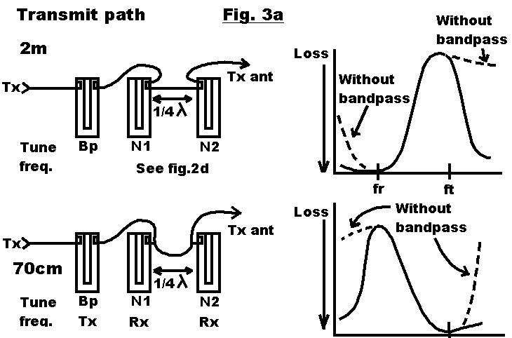
Transmit path.
|
|
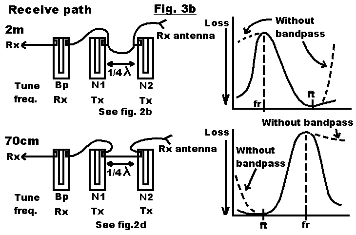
Receive path.
|
|
In the 2 metres transmit path and the 70cm receive path notches of mode 3 type can also be used:
|
|
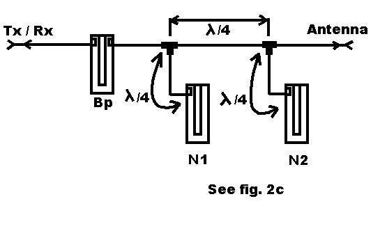
Interconnecting cavities.
If on 70cm notches like in fig. 2b (mode 2) are used, the interconnecting cables should be connected together as close as possible to the coupling link, so very close to the body of the cavity.
At a longer distance between the couplig link and the cable-coupling-point (T-piece), the notch wil be less deep. When the distance becomes 1/4 wave length, the notch becomes "inverted", like in fig. 2c.
| pa0nhc: If PTFE cable is used, the cables could be soldered directly onto couplinglink themselves. Some Procomm filters use this construction. You
then dont have to guess about electrical lengths of connecting wires, and very accurate cable lengts are then possible. Notches can be deeper.
On top of that, it saves connectors, money and possible trouble afterwards. But think about it, how to service the filters lateron. Is it then still possible? |
| pa0nhc: I learned from experience, that double screened PTFE coax, Aircell7, Aircom, and good quality N connectors with PTFE isolation and gold
plated contact pins are to be preferred. Especially on cavities and on the transmitter and receiver connections of the relay station. There will be less chance on HF-leaks and
cross-talk between transmitter, receiver and antenna connectors. N connectors are mechanically much more stable than BNC and guarantee better contact and less HF-leaks. On top of
that they are watertight.
Do not save money on those cables nor on connectors! If Aircell or Aircom cable is used, only use especially for this type cable designed N-connectors. Install N-connectors according official instructions onto the coax cables. Turn N-connectors tightly onto chassis parts, so they make good mass-contact. To prevent unwanted couplings and degradation of the painfully achieved isolation in the duplexfilter, coax cables should not run in parallel or close together. This naturally also applies to HF-cabling inside the relaystation cabinet. The use of a little special anti-corrosion oil (CRC 5.56) on all connector-contacts help to prevent corrosion in humid environments. Use PTFE cable only for short lengts, on places where thick double screened coax cannot be used, like for short bending, inside cabinets, and for directly soldering onto filter parts. Use only specially designed connectors! The only pluspoint on (double screened) PTFE cable is the heath-resistance. PTFE cable has more loss than f.i. Arcom and is much more expensive. |