|
|
Repeaters transmit and receive at the same time (through the same antenna) in the same frequencyband. Extra isolation between transmitter and receiver is therefore needed. A duplexfilter can provide this. The amount of extra isolation needed mainly depends on three factors:
1. The isolation of separate receiving and transmitting antennas or, if one antenna is used, the isolation of a circulator on the output of the duplexfilter.
2. The "Blockinglevel" and "intermodlevel" of the receiver input stages.
3. The amount of sideband-noise from the transmitter on the receiver frequency.
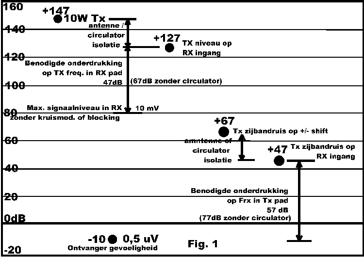
Diagram fig.1 shows some typical relative signal levels, presumed that:
a. the receiver shows no blocking and/or intermodulation when a signal of 10mV rms is present at the transmitterfrequency
b. the isolation between transmitter and receiver allready is 20db, due to the use of separate antennas or a circulator.
If the repeater is operated at one antenna, and no circulator is used, 20dB more isolation has to be made by using one more notch-cavity in the transmitter- and the receiver chain.
If the receiver is more sensitive (like the one of PI3RTD: about 0.16uV/12dB sinad), 10dB more isolation is needed.
|
|
Transmitter sideband noise.
For a "normal" transmitter, sideband noise-levels are -70 to -80dBc at (Ftx +/- shift). A carefull transmitter-design can improve this noiselevel by about 10dB, optimising cristal- and oscillator circuits, first multiplying stages, and filtering the wideband noise generated in audio stages and powersupply.
By reducing the drive of multiplierstages such, that just enough harmonics are produced, noise is reduced too.
Often neglected is the point, where the audio is injected into a phase-modulator. If a bufferstage is between the limiter/de-emphasis-circuit and the phase modulator, wideband noise of this bufferstage is noticable around the transmitter frequency. Remember: a phase modulator is twice as sensitive for each higher octave of modulation frequency. A phase modulator is sensitive for high frequency noise. A simple lowpass filter with a crossover frequency of abt. 10kHz on the input of the phase modulator can solve this problem.
A noisy powersupply also can degrade transmitter- and oscillator noise. Even 1mV powersupply wideband noise can couse noticable transmitter sideband noise.
Large-signal properties of the receiver.
The large signal properties of the receiver can be improved by using a "high level mixer", such as a hot carrier diode ring mixer or a balanced FET mixer.
The HF-preamplifier stage must have JUST enough gain, to compensate for the losses of the bandfilter between the preamplifier and the mixer, and the noise generated in the mixer itself. This preamp must, measured directly behind the mixer, couse 3dB difference in noise level when it is switched on and off, not more. It also must have a very good linearity.
HF-selectivity is an important factor. Designs using "Hi Q" helical- or lineair resonators between (antenna and HF stage, and) HF stage and mixer stage, allways prove to be the best.
The input matching circuit between antenna connector and the pre-amplifierstage must be low-loss, and must match for minimum noisefigure. The Q of this input matching network is not the most important issue, if the duplexfilter contains a bandfilter cavity (Q of 300 or so and low loss). It then only has to help to improve wideband selectivity, as a bandfilter-cavity gives a finite wideband isolation (30dB).
It essential, to use directly behind the (first) mixer a cristalfilter with good stopband rejection (90-100dB). Some filters provide good selectivity and adjacent channel suppression, but lack of isolation at 600kHz or 2Mhz frequency distance.
Max. optainable stopband rejection never can be better than the isolation between in- and output of this cristal filter. Good screening between in- and output of the filter is therefore also nessacery to prevent "jump-over" of signals.