|
|
The number of fieldlines which cross the window of the coupling link, determens the "coupling-factor" (see fig.6). The coupling has to be adjusted only once during first setup.
By altering the effective cross section of the link (by turning, bending or changing the diameter) the couplingfactor can be changed. Bending the link makes a simpler mechanical design possible, and is therefor recommended. The link, when in position, must then easely be reachable, f.i. through a small hole in the side of the cavity. This hole should be closed using a metal cap.
Links also can be installed in the toplid of the cavity. If they can be turned, coupling is easely adjusted. But, it makes a more difficult construction nessacery.
In the pa0nhc duplexfilter, after adjustment the links are fixed in the toplid by solder and glue. This construction is very simple, cheap and stable.
In a bandpass cavity (mode 1) the couplingfactor determens the 3dB bandwidth, in- and output VSWR and insertion loss.
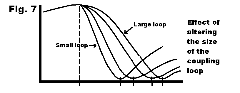
In a "notch-cavity" (modes 2, 3 en 4), the couplingfactor determens the frequency-difference between pass- an notch-frequencies (the "shift"). See fig.7.
Little finetuning of the passfrequency does not influence the difference between pass- and notch frequencies, VSWR, selectivity or insertion loss.
Position of links and fieldlines inside a cavity
|
|
|
|