Use airtrimmers of good quality.
|
|
Suitable ferrite circulators are avalable for the 150-175MHz and 440-470MHz bands. New, they are expensive, and have a wideband isolation of 20dB. If used on amateur frequencies, isolation is much less.
If such a circulator is provided with trimmer-condensors, it can be tuned exactly on the wanted frequency. Isolation upto 40dB is obtainable. (pa0nhc: after readjustment the circulator of pi2rtd made 30 dB isolation on 431.9 MHz).
TDK ELECTRONCS is producing circulators under the brandname "HEXALATOR":
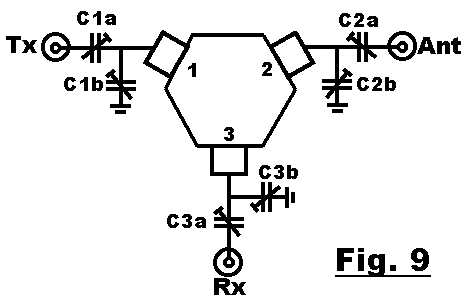
Matching a circulator to 50 ohms.
Use airtrimmers of good quality.
|
|
Practical suggestion:
|
|
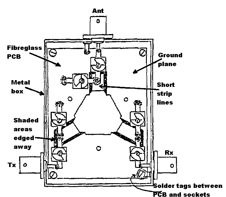
For 70cms an composite aluminium box is suitable for housing. On 2mtrs bigger trimmers are needed, and therefor a bigger housing.
| * | Screw the circulator on the housing, which then acts as a cooling element. |
| * | Screw the PCB at some distance from the housing, using metal standofss or filling-rings. The PCB must just make mechanical contacht under the circulator connections, without cousing stress. |
| * | Solder the circulator connections fast, using a big soldering iron. |
| * | Solder the mass-sides of the connectors to the mass-surface of the PCB. Use copperfoil or so. Use spring-rings between housing and copperfoil for secure contact, and to prevent oxidation (Al-Cu). If there is room enough, the connector-flanges could be put on the cabinet-inside, and then soldered directly to the PCB. |
| * | Connect the mooving plates of the trimmers C1b, C2b and C3b to the mass surface of the PCB. |
| * | Drill small holes in the lid, so adjustment can be done with a closed box. |
| * | C1a, C2a and C3a must be adjusted using an insulated trimmingtool. |
The adjustment of a circulator.
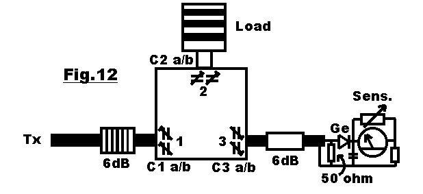
Note: During adjustment, all ports of the circulator must well be terminated with 50 ohms. Attennuators of 6dB or more must be placed between circulator, transmitter and detector, directly onto the circulator (see fig. 12).
|
|
| 1. | Set all trimmer Cs to the mid position. |
| 2. | Connect a 50 ohm dummyload directly to port2. Connect a sensitive powermeter to port 3. Connect a HF-source through a 6dB pad to port1. A roll of thin 50ohms coax can be used as a cheap attenuator. |
| 3. | Adjust C2a and C2b for minimal output on port3. |
| 4. | Turn the circulator 120 degrees to the left. RF source to port2, load to port 3, detector to port 1. Adjust C3a and C3b for minimum on port1. |
| 5. | Turn the circulator 120 degrees to the left. RF source to port3, load to port 1, detector to port 2. Adjust C1a and C1b for minimum on port2. |
| 6. | Repeat points 2-5 until no improvement is possible. |
| 7. | Fine-adjust if nessacery, on location when connected to the repeater antenna. |
| 8. | Comparing input to port 1 and output on port 2 should show an insertionloss of about 0.5dB, as well between ports 2 and 3. |
| pa0nhc: In my opinion, if a circulator is used, the VSWR of a duplexfilter should be as close as possible to 1:1.0 on the passfrequencies. Especially, if the connecting cables are an odd number of 1/4 wavelengts long. Otherwise, in practice, the measured properties of the circulator can not be reached. |