| << |
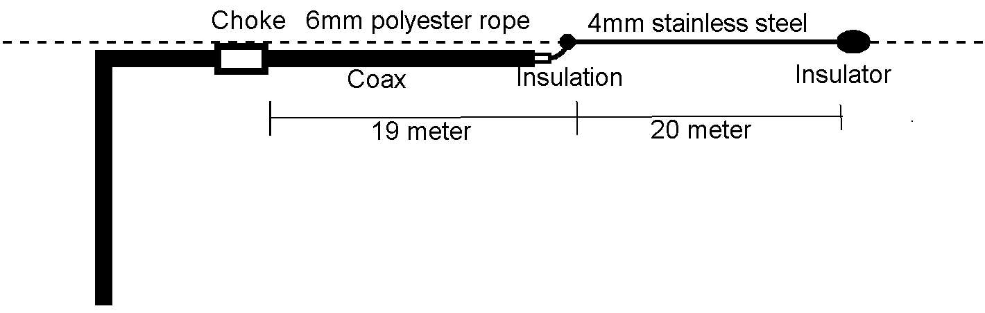
Pa0nhc "Cobra antenna". |
|
|
From ARRL handbook 2022 For extra 1.8 MHz add : |
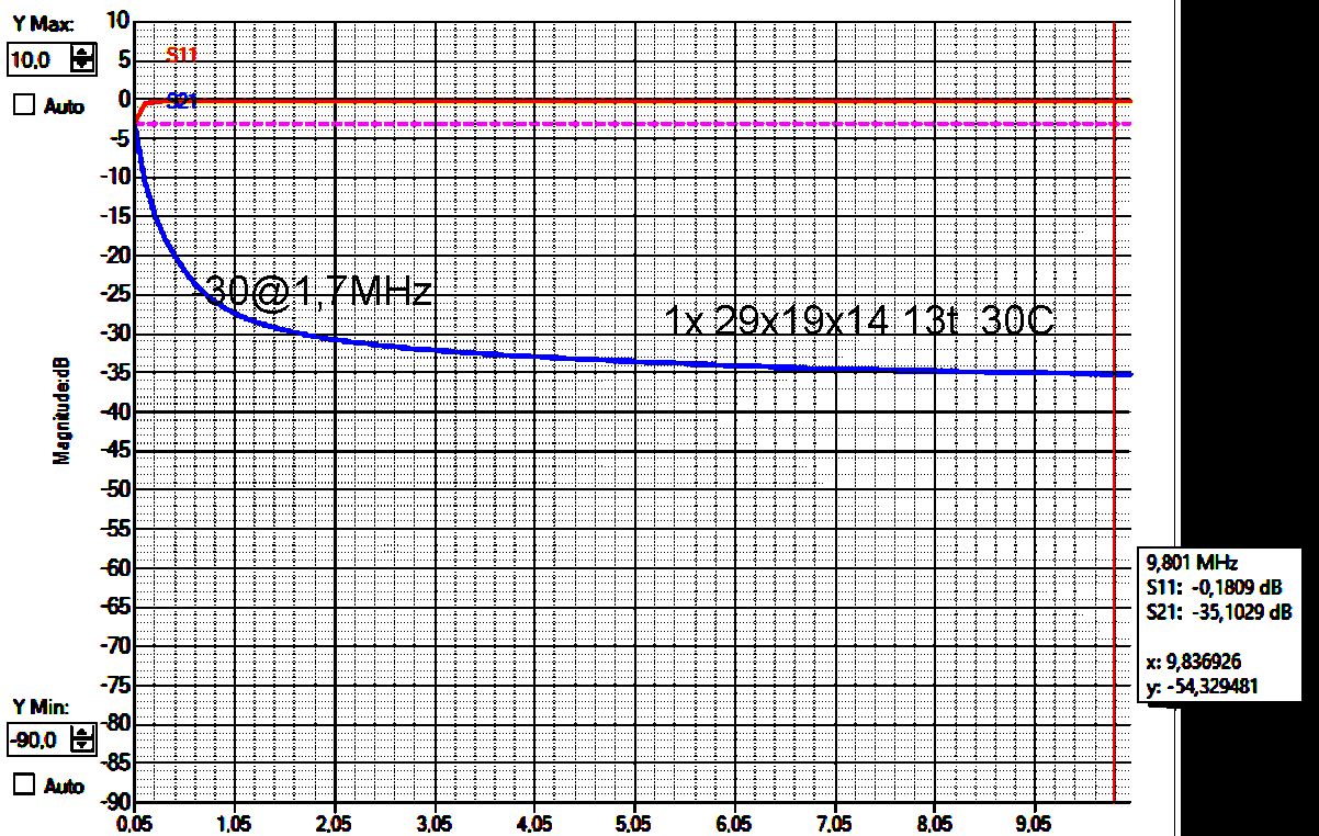
Measurement on one small
29mm #31 core, When 7 of these small coils are
connected in series, their combined impedance will rise on every
frequency to about 7 times or 17 dB. |
Oly use coaxial chokes for a coaxial
cobra antenna.
A two wire CMC is NOT
approoved for
this Cobra antenna. A two wire choke interconnects the inner and outer surfaces of the end of the dipole.
The inner screen surface is there then no longer insulated from outer
screen surface.
This antenna will then not be a coaxial dipole, but a strange form of end-fed
radiator !
=>> ONLY use a coax CMC for connecting a coax to another coax, or a (coax) feeder to a coaxial antenna part.
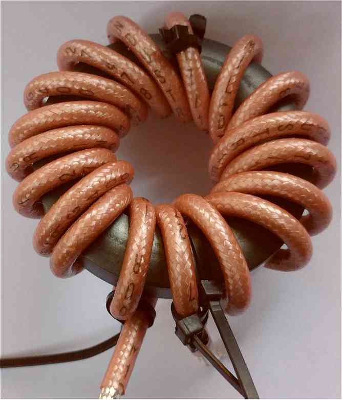
Choke coils for 400W.
All chokes (CMCs) are
wound with Belden H155 coax or RG400 coax each on one FairRite 61mm #31
core.
Do not use other ferrite mix !! Order FairRite
partNr. 2631803802
61mm cores from industrial sellers like mouser.com.
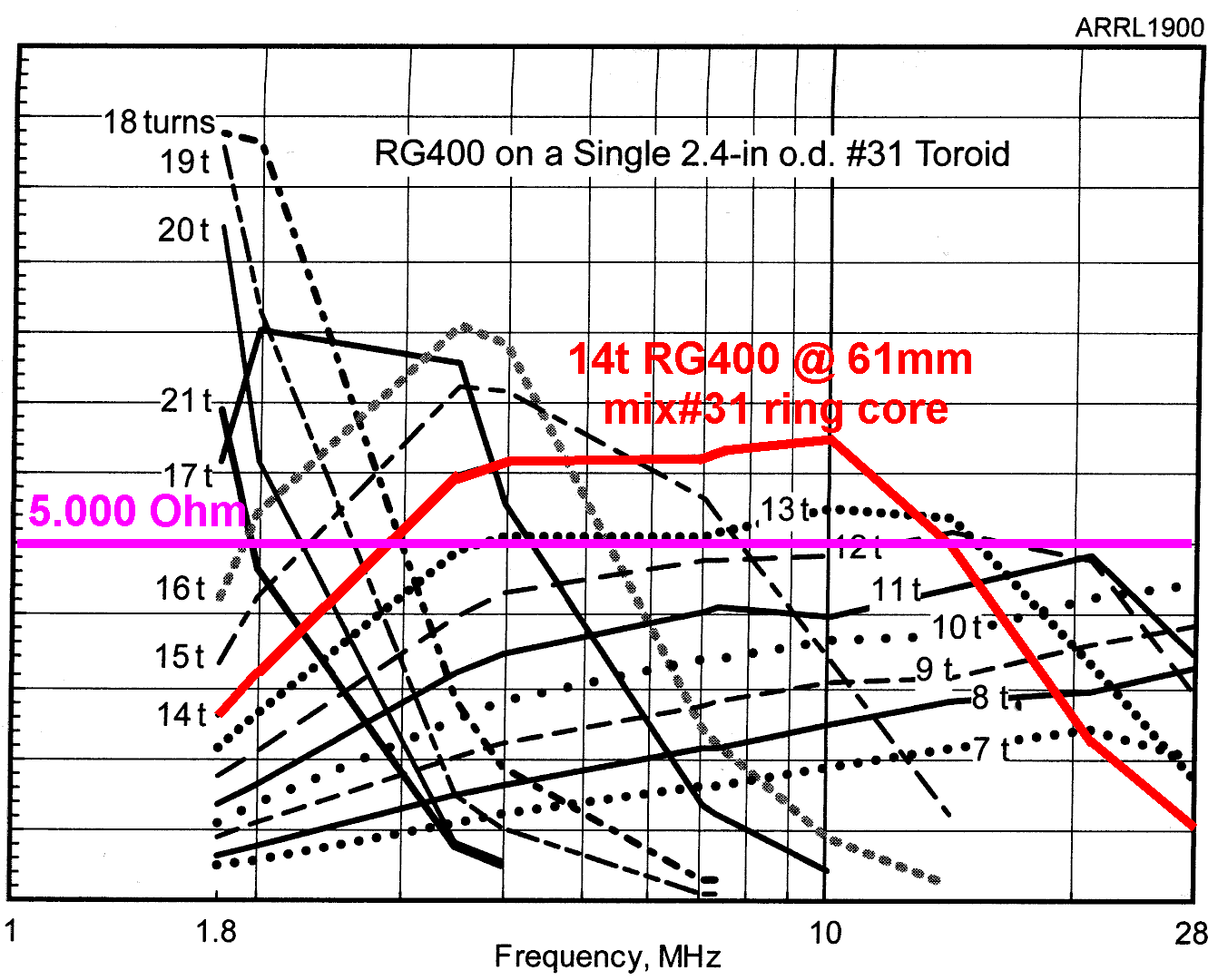
Choke set for 3.5 to 15 MHz : 20220331.
Wind three coils each with 14 turns coax.
Connect these three coils in series.
The estimated total impedance of these 3 chokes connected in series : >=
15 kOhms between 3MHz and 15 MHz.
Choke set for 1.8 to 15 MHz : 20220331.
If you want the antenna to be used on 1.8 MHz too, then connect an
extra 4th choke in series :
18 turns wound at 61mm mix #31 ring core.
Choke losses and heating of cores.
The end of the dipole is high-Z, estimated to abt. 2 kOhms.
With 100W power, the radiation-loaded dipole-end-voltage is probably 225 Vrms
(320Vp).
With a choke impedance of 15 kOhms, the choke leakage current is abt. 15mArf.
The total choke dissipation is then abt. 3.38 W.
Each choke
coil will be heated by abt. 1.13W.
Choke heating is no worry, as the coil coax warms up, and is cooled by air.
The core
stays cool.
General rules for coaxial chokes :
- 5.4mm Belden H155 double screening
and small bending radius, moist resist foam dielectric
!
- 5.3mm RG223/U silver plated, double
screening and small bending radius.
- 5mm RG400 PTFE silver plated, double
screening and small bending radius. For more than 14 turns.
- One time through the core hole
= one turn.
Easy counting of turns :
Number of turns = number of external loops + 1 .
- Wind close to the core !.
- Wind in one direction, do not wind back.
- Inside the core hole :
wind the turns beside each other, not
over/under.
Fixing slippery PTFE windings to the core.
Fix the PTFE winding at the begin, the end, and in between
to the ferrite core as follows :
- Loosely close a first tie wrap around the core.
- Push a second tie wrap between the first one and the core.
- Close the second tie wrap around the coax turn.
- Tighten both tie wraps.
- Clip off excess tie wrap ends.
 Choke construction.
20220401.
Choke construction.
20220401.
Keep at least 2cm distance between all
chokes, and between chokes and metal surroundings.
The chokes could be, each separately,
supported by the antenna rope.
The chokes could be shifted over a piece of PVC pipe, which on the ends has N-connectors,
and is supported by the polyester suspension rope.
The chokes could be fixed onto a piece of plexy glass, which is supported by the
polyester suspension rope.
All can be constructed
at fore hand, inside the house, even
during very bad weather as follows.
Inter connecting, water proofing and installation outdoors is later on
easy during good weather.
Make at fore hand :
- The antenna choke with waterproof N-connectors ,
- The feeder common mode chokes with waterproof N-connectors and
- The inter connecting feeder coax pieces.
For all coax use Belden moist resist
H155.
Outdoors, during good weather :
- If needed, the chokes and cables fitted with N connectors are easily
connected or removed, exchanged, repaired.
- A piece of UV resist plastic tube can function as carrier for the
chokes.
- In each open tube end an end cap is glued, containing a water proof N-female
bus.
- Then all coils are connected in series, and connections are insulated by
crimp hose and Vaseline..
To prevent water intruding the
antenna coax and transmission line coax :
- At the tube inside, the N-busses should be well water proofed (sealing with
thermal glue or two component glue).
- When connecting N connectors, be generous using petroleum jelly (Vaseline) :
- on the connector inside
- on the threads
Remove all Vaseline from the outside of the connection.
Wind with
self-vulcanizing butyl tape, with 50% overlap.
Do NOT pull the tape to
break it. Cut it with scissors.
The wind all with a layer of good
insulation tape
with 50% overlap.
Do NOT pull the tape to break it. Cut it with
scissors.
OR
- Put a generous layer of Vaseline onto the
outside of the connected pair
- Crimp the connected pair and the coax
and with crimp hose.
- Vaseline should then be pressed out.
- Remove excess Vaseline.
REM Water inside a coax changes its
properties dramatically, causing mismatch and performance decrease.
And it can lead to water leaking at the transmitter end.
Moist coax
cable largely changes its impedance and losses, and must be exchanged for new
coax.
Prevent it by using moist resist H155 coax and careful water proofing.