|
|||
|
|
|
Low noise, high IP preamplifier for 10Mhz to 500MHz. |
(C)
The use, copy and modification of all info on this site is only permitted for non-commercial
purposes,
and thereby explicitly mentioning my radio amateur call sign "PA0NHC"
as the original writer / designer / photographer /publisher.
|
|||
|
|
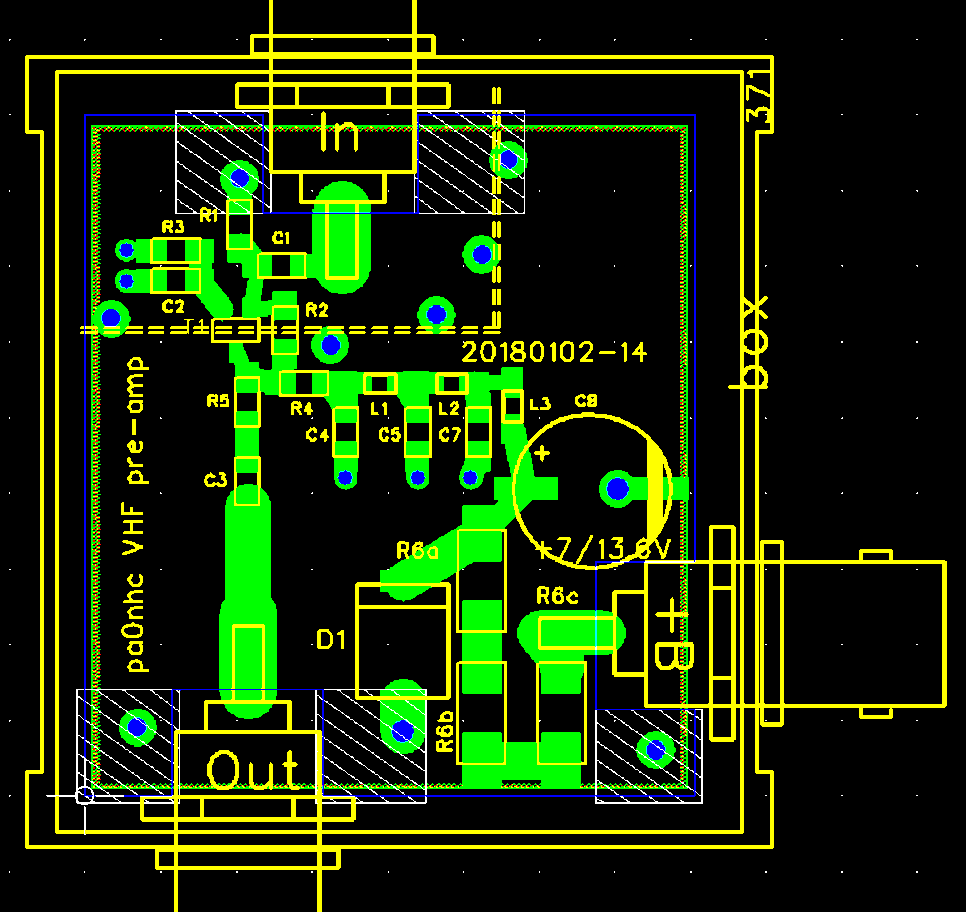
| Using the factory made PCB | Using your DIY PCB |
This amplifier unit is wide band, has no selectivity, Zin and out are 50 Ohms, and is universally usable as low noise pre amp for 28MHz to 440 MHz.
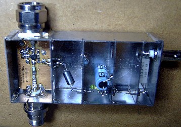
Sensitive, sturdy.
Without any damage, acting as sensitivity optimizing components in very
critical and difficult circumstances with an antenna height of 105 m above
street level.
Two of these pre-amps served more than 10 years with both 2m and 70cm repeaters in Rotterdam.
Uncritical construction. Just solder.
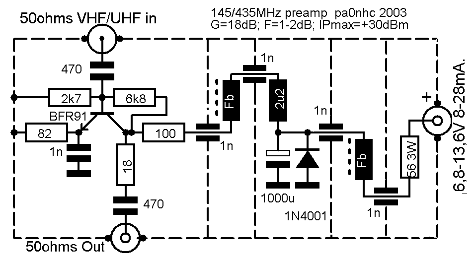
Zin/out: 50 ohms (PCB signal tracks are 50 Ohms).
Uin(max) 40mVeff @ Ub=13,6V and f=145MHz (Ib=28 mA).
Sensitivity: 12dB sinad <= 0,125uV 1/2 EMF.
Voltage gain: 18dB @ 145 MHz.
The amplifier is sturdy, insensitive to power voltage changes and proved to overcome severe static's.
The diode prevents damage in case of reversed power or nearby lightning.
The 3W lowers the supply voltage to 12V, and limits peak currents when switched-on.
At a supply voltage of 13,6V is has the highest IP, and is most tolerant to very strong
non-wanted signals.
Transistor dissipation is then 270 mW.
At lower supply voltages (6.7V) it has a bit lower noise figure, but lower IP.
In case of fault, the amplifier can be changed easily for another amplifier, or simply omitted, and is therefore service friendly.
The necessary selectivity must be connected directly to the INput.
The very selective DIY helix band pass filter
described elsewhere on his site is highly recommended for 145MHz use.
As in- and output impedances are 50 ohms, standard helix band pass filters 50 ohms for 145MHz or 435 MHz (Toko), can be connected directly to the amplifier.
The power connection can be any coaxial
type.
BNC is handy for power too, as standard screened coax cables can then be used.
History.
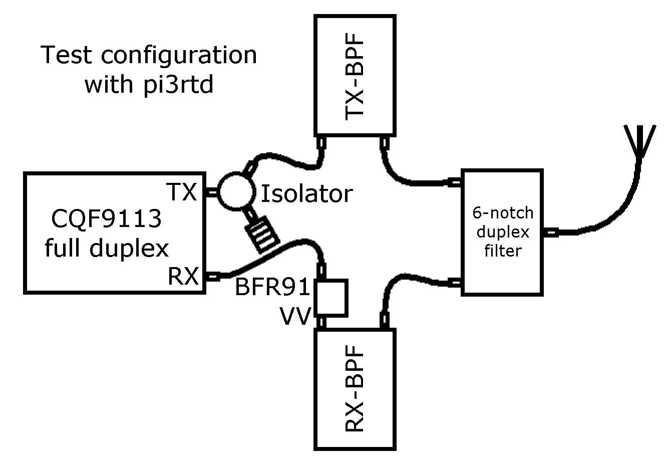
The preamp was developed for, and tested with our 2m and 70cm relay stations (pi3rtd and pi2rtd). Their duplex filters had over 90dB separation, and very good selectivity due to
the application of extra cavity band pass filters.
With pre-amplifiers connected, the repeater receivers showed no sign of desensitization nor IMD when the repeaters transmitter output power was varied from QRP (< 1W) to QRO (>40W!).
REM :
During testing it became clear, that the preamplifier had to be connected directly onto the output of the band pass filter.
If the amplifier input was connected to the input band pass filter through a coax cable, the amplifier could become instable at certain cable lengths, due to extreme
mismatches at certain frequencies.
The best solution therefore is to screw the amplifier input directly onto the output of the receiving band pass filter, as shown in the drawing above.
Why installing a preamp outside a repeater casing.
Due to installing a preamp outside a repeater transmitter cabinet :
- best results will be obtained, as no direct radiation from the transmitter into the preamplifier housing is possible
- the construction is simpler
- if an amplifier should become defective, it easily can be exchanged, or just be omitted in case of emergency.
- one type wide band preamplifier is suitable for both 145MHz and 435MHz repeaters.