| << |
pa0nhc 75dB / 1dB 50 Ohm step attenuator 20180829 |
Copyright.
The use, copy and modification of all info on this site is only permitted for non-commercial
purposes, and
thereby explicitly stating my radio amateur call sign "PA0NHC" as the
original writer / designer / photographer / publisher.
Preliminary development information.
|
|
|
|
|
|
This project can be costly when good parts are used : Switches can cost up to 60 Euro. A painted box up to 20 Euro. Two BNC busses up to 10 Euro. 30 resistors cost abt. 3.30 Euro + postages.
Use good quality switches, and BNC busses with PTFE (Teflon (r) insulation. A few tenths of an ohm extra internal resistance ruins the attenuator specifications.
If
switch contact resistance prove to become unstable :
Put two or three drops of CRC2-26 or CRC 3-36 (conrad OrderNr. 886384) fluid into the opening of each switch
shaft.
Firmly change all switch positions twenty times from attenuated to non-
attenuated and back.
After a few days, again actuate the switches twenty times. Then check the attenuator impedances and attenuations.
The CRC fluid will lubricate the mechanism, AND removes possible contact oxide and sulfide (over 50 years experience !). Most of the CRC evaporates in time, but it leaves a very thin oily layer, thereby isolating contacts from air, and preventing oxidation.
General
:
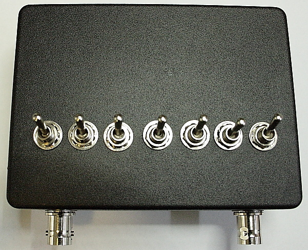
This design uses small sized toggle switches with round 6mm shafts. As a result, the
PCB is
as short as possible,
resulting in as low as possible PCB and housing costs. The PCB fits into a A Hammond 1590S die cast box.
Drawings for drilling the
round holes are
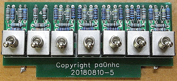
available. Easy assembling of the PCB is ensured by using 1mm
component holes, exact fitting switch contact holes, and axial wired, 2.5 x 6.5mm, 0.25W metal film
resistors.
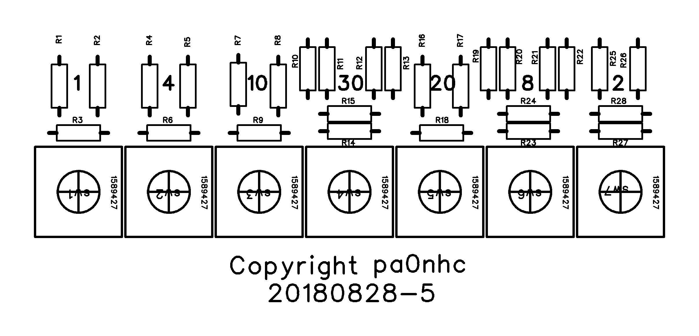
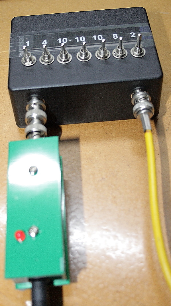
Attenuation : (1 + 2 + 4 + 8 + 10 + 20 + 30) dB = Max. 75dB in 1dB steps.
In- and output : BNC busses, 50 Ohms, max. power 0.25W.
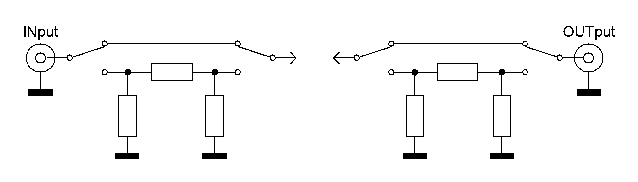
All stages are of the "PI" type and can be connected in series by switches.
Accuracy : +- 0.2 dB.
The PCB full mass plane helps to achieve a wide frequency range. It makes mass circuits low-Z, and reduces the influence of resistor self inductances, due to small capacitances between the resistors and the mass plane. Signal lines have minimal length, and 50 Ohms impedance. Reasonable accurate resistor values and attenuation are obtained, by connecting two 1% resistors in parallel. An open switch position showed only -60dB or better cross talk.
Building :
The Hammond die cast box has tapered sides. The dimensions in the
drawings are in respect to the open LID side. The bottom side is
2 x 0.75mm smaller. Keep this in mind when marking the locations of the holes on
the bottom. A
painted box is recommended, as the paint quality and durability is better than
of own sprayed paint. It is worth the money.
1. Draw the hole positions onto the box using a pencil.
2. Punch center pits as drilling guides.
3. Start drilling with 2.5mm. Enlarge with 4mm. Drill all holes with 6mm. Drill BNC holes with 9.5mm.
4. Solder all resistors into the PCB.
5. Place the switches into the PCB holes. Do not solder yet. Put the
switch handles all in the non-attenuating position.
The PCB now functions as an anti-rotation guide
for the switches.
6. Slide the PCB with switches into their holes in the box.
7. While pressing onto the PCB, place the tooth rings and nuts on the outside of
the box over the switch
shafts. Turn the nuts tight.
Try to avoid torque onto the
switch contacts.
8. Turn the box with its open side up.
9. Press the PCB firmly and tightly onto the switches.
11. First solder only one pin at switch 1 and
switch 7. Check that the PCB is in parallel with the box.
12. Then solder all other switch pins. Do not overheat to prevent switch contact
dislocation.
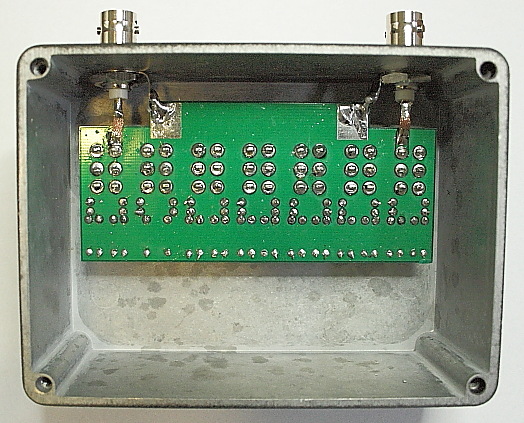
13. Install the BNC's, with the locking tooth rings on the outside of the box,
and the ground lugs on the inside.
Lugs must point towards the PCBs ground solder surfaces.
14. Turn the BNC nuts tight. This could be done as follows:
Put a spare BNC plug on the BNC bus.
Clamp this BNC plug in a vice.
Using pliers, block the nut and
the solder lug against turning in respect to the housing.
Turn housing + nuts + solder lug +
pliers as a whole, until the BNC bus is firmly locked.
14. Solder the BNC ground lugs to the nearby PCB mass surfaces.
15. Temporarily put a BNC plug onto the
BNC bus, to prevent dislocation of the BNC signal pin, before soldering the BNC signal pin to the PCB.
16. Stick four plastic feet at the outside of the lid, near the corners, and screw the
lid
onto the box.
17. Glue a attenuation identifying scale to the top of the box.
 Checking nominal attenuator in- and output resistances :
Switch-on a digital ohm meter, shorten its wires and note the displayed value (abt. 1
Ohm). This is the internal resistance of the measuring cables.
0dB
attenuation :
Put all switches in their non-attenuating position.
Connect a 50 Ohm dummy load to the right hand attenuator port.
Connect the digital ohm meter to the left hand attenuator port.
The shown resistance value should be a little higher than 50 Ohms (the 50 Ohm
dummy load resistance +
meter wire internal resistance).
Stage impedances :
Put the most right switch into its attenuating position. The meter indication
should show the same value.
Put the switch back in non-attenuating position.
Put the adjacent switch into its attenuating position. The meter indication
should show the same value.
Put the switch back in non-attenuating position.
Go on until all stages are checked.
Reverse meter and dummy load connections.
Check stage impedances again like above.
Stage attenuations :
The to be used receiver should have a calibrated dBm or dBfs signal strength
indication with a resolution of 0.1 dB.
Use for
instance a software defined radio. I used an Airspy HF+. To prevent overload and
wrong readings, adjust the receivers input attenuator so, that the indicated signal strength
is not higher than -20dBfs.
Connect a signal generator (having 50 Ohm output impedance), with the step attenuator in series, to the 50 Ohm antenna input of a receiver.
Put all attenuator switches into their non-attenuating position.
Change each switch from non-attenuated into its
attenuated position and back. The indicated attenuation should be within +- 0.1dB to the intended
stage value.
Change all switches from their non-attenuated to their attenuated position. The total signal attenuation should be 75dB +- 0.2dB.