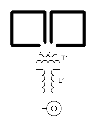
 Schema. * start of winding. |
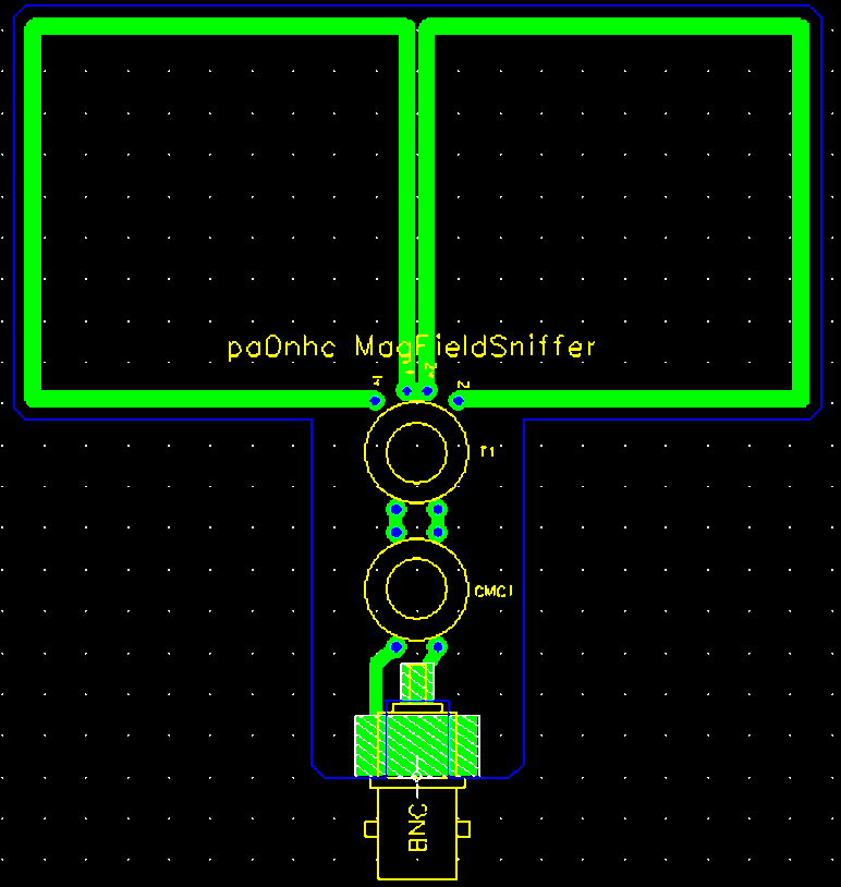 PCB design, abt. 95 x 95 mm. A piece of 32mm PVC pipe could serve as handle. |
 Test example together with my microwatt meter. |
| << |
MagFieldSniffer. |
Schema. * start of winding. |
PCB design, abt. 95 x 95 mm. A piece of 32mm PVC pipe could serve as handle. |
Test example together with my microwatt meter. |
| The original idea is from |
Properties.
This little balanced magnetic (H-) field antenna has a symmetrical structure and
equipped with matching transformer and a balanced to unbalanced common mode
choke. Its eight sides are are 45mm long. The 50 ohms output is asymmetrical,
and matched to the antenna through a 12 : 1 : 1 transformer. Its wide bandwidth
is abt 1MHz to 25 MHz due to the very low loading (abt. 1.4 Ohms), and its small
size compared to the wave lengths of interest.
It can be used for :
- Finding magnetic noise radiating equipment.
- Finding common mode currents along
Coax cables,
Balanced transmission lines,
DC and AC power cords,
- Checking the effectiveness of common mode chokes on antenna
feeders,
- Using very low power, determining the current distribution along antenna
parts like radials, radaitors and feed lines.
- Wideband E-field antenna for EMV-spion,
a special noise finding wideband receiver.
- Noise sampler for a "noise cancellar".
- Antenna for a magnetic field strength indicator.
A long thin coax connection will here
not cause much cable losses, as the antenna is matched to 50 Ohms.
Test results.
- At the front of a plasma TV screen, several locations of noise sources
could be identified.
- At the front of an LCD TV and an LCD PC monitor no noise sources could
be found.
- At the back of that LCD TV screen one strong noise
sources (its SMPS?) could be identified, although it was behind a steel cabinet
cover.
- At a 12Vdc/30A linear power supply with 20 A load, a weak (50 Hz?) mains
transformer field could be identified.
- At several (only little RF noisy) SMPS 5Vdc power plugs very weak
E-field noise could be identified.
.
Winding.
Transformer T1 is wound onto a HF 25 MHz wideband Ui=125 ring core
1/2"diameter (FT50-61).
Use 1mm diameter insulated wire, for instance one straightened wire wire pulled
from a piece of CAT5 network cable.
First wind the 12 primary turns, close to each other, in one direction through
the hole of the core. All turn beside each other (not over nor under each
other).
Secondly wind the secondary turns in one direction, 2 x 1 turn aside each other.
When connecting, mind the correct phase (see the diagram).
Connect the center of the secondary winding to the center af the antenna.
Wind the common mode choke (balun) L1 onto
an 1/2"
FairRite MIX#31 core.
Use two equal lengths of thin 0.25mm enamel (lacquered) coil wire.
FIRST TWIST this wire pair 3 full turns per cm while pulling it straight.
Wind and fill the core over 340 degr. circumference, in one direction.
Every turn must lay close beside the former turn, without overlap, nor underlap.