|
|
|
|
|
|
Download files:
|
PCB MASK (PNG 2400DPI) |
||
|
|
|
 Topsilk |
 Bottom copper |
 Prototype |
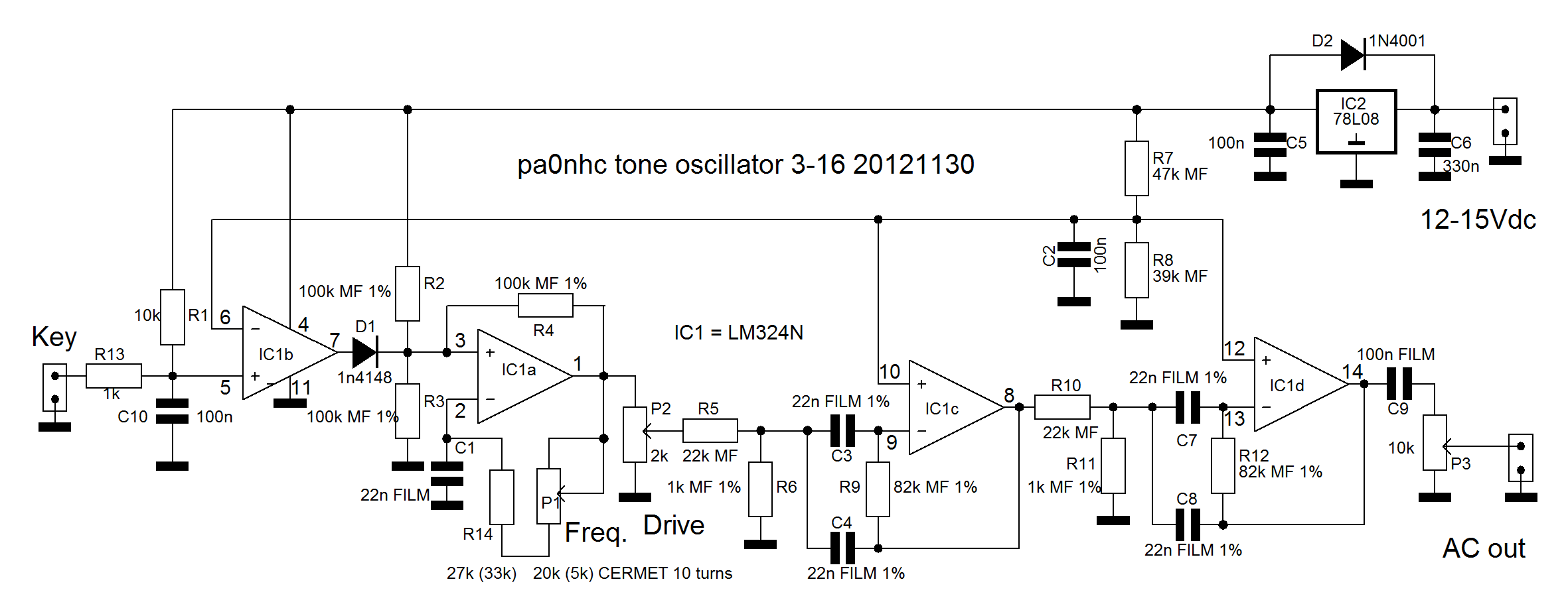
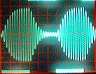 The double active bandpassfilter in IC1c and IC1d removes not only all frequencies above the fundamental,
but also the frequencies below it. The result is a remarkable clean signal without sharpness nor key-clicks. But still fast keyable.
The double active bandpassfilter in IC1c and IC1d removes not only all frequencies above the fundamental,
but also the frequencies below it. The result is a remarkable clean signal without sharpness nor key-clicks. But still fast keyable. But:
1750Hz and CTCSS (sub audilbel tone) filters in repeaters are very selective. These tones must be generated accurately and stable. This calls for a stabilised power supply, and
temperature stable metalfilm resistors and FILM capacitors for C1, C3, C4, C7 and C8.
Exept NP0 types, all ceramic capacitors change with applied DC and AC voltage and are aging in time. They are NOT stable. Only useable for decoupling. Not for
coupling.
P1 MUST be a CERMET 10-turn trimpot for reasons of exact adjustment and frequency stability. Best use a 1K value or even less. A low value helps for easy and accurate
adjustment.
You can use R14+R14a for course setting of the oscillator frequency (totally approx. 33-34 kOhms (27k + 5k6)).
C1b can be used to adjust the wanted tone frequency into the middle of the adjustment range of P1.
In several prototypes the circuit showed a slight POSITIVE temperature coëfficcient (ca. +0.5% for ca. 30C up). C1b could be a POSITIVE temperature coëfficient ceramic capacitor
to compensate it. The used values must be calculated with the used capacitances in mind.
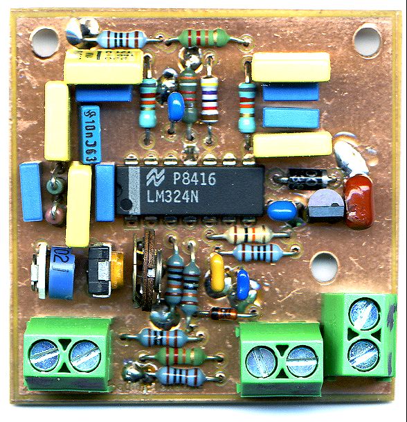
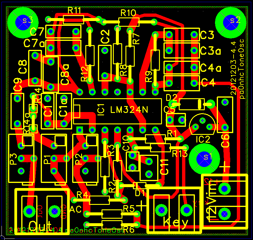
Assembling.
The here wanted filter capacitor values are mostly not standard values. For each of C1, C3, C4, C7 and C8, two places in parallel are reserved on the PCB. You can combine two
capacitors for one exact value.
Tolerances of capacitors can be 10%. It is wise to measure the capacitor combinations before soldering them in. The pairs should be +/- 1% of the total calculated
value.
Using a cheap, modern digital multimeter, suited combinations can easily be selected.
---
Drill all holes 0.8mm.
Drill the holes for D2 and the connectors 1.2 mm.
Dril the screwholes 3.5mm.
Before assembling parts, connect the mass planes of the PCB to the soldering irons mass, to prevent static damage.
Solder IC2. Solder pin2 on both mass planes. Solder bottomside first.
Solder first C5, then C6. Allow for a little space between the capacitor and the top copper plane. Solder bottomside first. Solder their mass pins on both mass planes.
Solder D2.
Solder IC1. Solder pin 11 on both sides.
Solder D1.
Solder the resistors. Solder the mass connection of R3, R6, R8, R11 on both planes.
Solder the remaining capacitors.
Solder P1, 2, 3.
Solder the PCB connectors.
---
Pre-adjust the trimpots until :
at P1 you measure 34kOhm between Pin 1 and 2 of IC1,
at P2 you measure 1 kOhm between its mid connection and mass,
P3 is at max position (0 Ohm between its mid connection and C9).
Setting up:
| 1 | Connect an oscilloscope (10V range) or a multimeter (2Vac range) to "Output". |
| 2 | Connect 12-15Vdc power. |
| 3 | With a high-impedance (digital) multimeter check that the voltages on IC1-4 is 8.0Vdc and on IC1-6-10-12 is 3.6V dc. |
| 4 | Connect "Key" to mass. |
| 5 | Tune the frequency with P1 to max output on the scope or meter. |
| 6 | Adjust P2 for max. undistorted output, then turn back to 80% of that value. |
| 7 | Readjust P1 for the wanted frequency. Up to + or - 10% from the filter center frequency is allowed. |
| 8 | Readjust P2 for 80% of max. output. |
| 9 | Lock P1 and P2 with wax, glue or nail lacker. The final output voltage shall from now on be adjusted with P3. Do not change the adjustments of P1 nor P2 anymore. |
|
A subaudible tone may >>NOT<< be injected somewhere in the microphone audio amplifier of a transmitter ! |
An accurate adjustment method for a sub audible tone frequency (CTCSS tone).
Because subaudible tone detectors in repeaters have a very narrow bandwidth tone filter, the tolerance for the subaudible tone frequency is very
small.
Definitive adjustment should be done when the PCB (transmitter) is warmed up to abt 35C.
- Connect the tone output to the X-input of a oscilloscope.
- Connect the Y-input to the data-output of the receiver (in a good receiver the sub audible tone is filered from the speaker signal, and not measurable there).
- Switch the oscilloscope in X-Y mode and adjust X gain and Y gain and position.
- Tune the receiver to a repeater which sends the desired tone frequency.
- Tune P1 to a still-standing ellips.
- Test the temperature stabilty by heating the PCB several times up to 50C using a hair dryer, and cooling it down.
The tone frequency is accurate enough, if on the oscilloscope the ellips turns around fully 1 time after a longer peroid than 12s time.