|
|
Big improvements made to MXL990 and MCA SP-1 condenser microphones. |
pa0nhc re edited 20110422
Warning 201305 : i do not know if this mod also applicable is to newer versions of the mXL990,
which contain SMD parts.
By modifying the electronics circuit the performance of these mikes can be improved :
a. 11dB higher maximal undistorted output
b. wider flat response below 80Hz.
c. no inter modulation distortion at high levels
d. vast suppression of espacially hum, and noises injected on the microphone cable.
Experiences:
No noises noticed during a critical recording, while a lot of power cables from a thyristor regulated stage lighting installation running near/over
my microphone cables.
The microphone manufacturer states a sensitivity of -40dBv/Pa. In practice it seems to be ca. -36dBv/Pa.
NB: not all parts have the same values as in the modification descriptions.
Some high parts are glued together or to the board to make them shock proof.
(Keep the very-high-Z connections of Q3, C13, R8, R9 and the insulators free of fingerprints, dirt and glue !).
Notice that in the SP-1 some cereamic condensers are replaced by film type condensers.
Film capacitors are far more temperature stable, and therefore guarantee close matching in order to keep high suppression of cable noises in all circumstances. AND film capacitors
also do not make in sputter noise nor Inter Modulation Distortion like ceramic C's can do.
Tantalum capacitors also are NOT recommended in audio circuits. They have a bad reputation as noise generators !
|
Schematic diagram of MCA SP-1 and MXL990 microphones.
|
Schematic diagram for MODIFIED SP-1 / MXL990 (* = modification)
|
The diagrams are shown in half size. Right-click on a diagram to copy, save and print it in
full resolution.
Both microphones use the same external biased capsule and electronic circuits. The part numbers mentioned are identical for both mikes, and given on
the circuit boards.
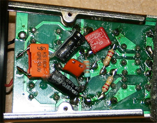
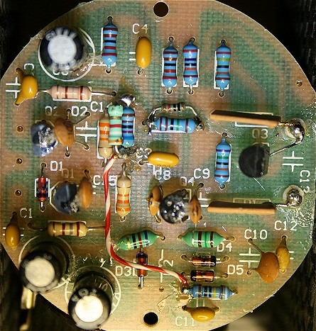
The MCA SP-1 has a separate oscillator board. In the newer MXL990 all the electronics are on one single sided PCB.
Modification description:
|
Prevent damage to the electronics due to static charges (especially to FET Q3):
- Connect the mass of the soldering iron to the mass of the microphone (using a wire).
- Connect your body to the mass of the microphone (using a wrist strap). |
a. Setting up T1,2,3 in "Class A" :
1. Connect ca. 18 kOhm in parallel to R13 . If necessary adjust the value of
this resistor so, that Us = ca. 2,65V).
2. Connect 3,9 kOhm parallel to R5 (this makes Ic and Uce of T1 and T2 higher so they do saturate at a higher output level).
3. Replace R3 and R4 both by 56kOhm each (for a higher base idle current, resulting in symmetrical saturation).
b. Improving the low frequency response and 50Hz cable-hum suppression.
4. Replace C3 and C4 each by, or connect 4,7u/63V electrolytic (NO tantalum) capacitors in parallel (the + wires connected to the bases of T1 en T2).
c. Improving middle frequencies noise suppression.
5. Replace R1 and R2 each by 180 Ohm 0,5%
NB: it also makes sense to exchance T1,2 by transistors having equal current gain. This ensures equal output impedances of T1,2 (ca. 40 ohms).
Transistor current gain can be measured using a cheap digital voltmeter with transistor function.
c. Improving high frequency noise suppression.
6. Replace C1 en C2 each by 22n film capacitor 0,5%
In 4,5,6 paired components give the best results, 1% difference between pairs result in 40dB (100x) noise suppression without further fine
tuning.
Remarks and motivations.
Ad 1,2,3 :
Check:
Us(T1) = ca. 2,65V ! . If this value differs to much, then adapt the value of the 18 kOhm resistor which was
connected in parallel to R13.
U(R7-R5) = ca. 12,1V.
U(R3/R4) = ca. 25V ! . If necessary, lower the value of the resistor in parallel to R5 in order to get 24 to 25V. The Uce of T1 and
T2 should now be at least 1,7V.
U(XLR2/3) = ca. 27,7V (the current drawn is now ca. 2x3mA).
NB: De manufacturer stated max audio level of 134/135dBspl and a sensitivity of -40dBv/Pa (10mV/Pa). Before modification, the measured maximal
undistorted output was only ca. 2x0,66Vpp = 0,47Vrms = -3dBv. Hereof the max. mike input level can be calculated at only 40+94-3 = 131dBspl.
After these simple modifications my mixer input was overloaded BEFORE the microphone electronic circuitry was! My six
microphones max undistorted output were measured at 2,5Vrms = +8dBv. Max. expected mike input level should now be 40+95+8 = 142dBspl !
Ad 4 :
For both microphones in the specs the frequency response show a roll-off below ca. 80Hz. The input impedance (for audio signals !) on both bases of T1 and T2
is less than 8 kOhm. This is far lower than the value of the original 150kOhm base bias resistors. The value of the coupling condensers C3 and C4 (0,33uF) now is obvious to
small for a good low frequency response. By enlarging their value, the low frequency response can be improved.
If possible use paired film or electrolytic condensers for C3/4 (measured with an capacitance meter: a
maximum capacitance difference between C3 and C4 of only 0,5% is wanted for a balancing effect better than 40dB at 50Hz down to 10Hz). This can be difficult to obtain.
By replacing C3 and C4 with large value electrolytic capacitors, their reactance become very low compared with the imput impedances of T1,2.
The remaining differences in capacitance value (thus reactance) are then of little effect on the 40 ohms output impedance of T1 and T2.
50Hz hum suppression now is good without matching C3,4.
Ad 5 :
R1,2 MUST be paired resistors for best balancing effect at the very important middle frequencies where the ear is most
sensitive for noises !
T1 and T2 should be best close matched in current gain, for equal output impedances.
Ad 6 :
Pairing C1,2 is effective for the high frequencies balancing effect (above 5kHz). Resulting in best suppressing of mains switch clicks, thyristor rattle etc.
NB: in critical audio circuits do not use ceramic capacitors because they
a. have bad temperature coefficient
b. can make sputternoises
b. can cause signal distortion due to varying capacitance at high DC and AC output voltages.
So here, in this critical audio application, use FILM or electrolytic capacitors.
Results:
Without any fine tuning, mods 4, 5 and 6 already give:
- a balancing effect of 30dB between 50Hz and 15kHz
- a far better suppression of hum and on the mike cables induced hum and noise (mains, appliances).
Resulting in a far quieter microphone in difficult circumstances.
- the output impedance now really is the 200 ohms stated by the factory.
IMD :
Especially in the single sided board of the MXL990, some HF oscillator signal unavoidably will be injected into the very high-Z gate of FET
T3. Some people believe that Inter Modulation Distortion could result in T1,2 .
- By enlarging the values of R1,2 , the capacitive load from C1 and C2 to Q1 and Q2 now is 4 times lower. So there is far less chance on inter modulation distortion due to
parasitic HF-oscillator signal present here.
NB: During critical measurements after the modifications, i could not detect any inter modulation distortion.
Tip: If R2 is optimally adjusted by a trim pot, an even better balancing effect is possible. (See: The measuring method ).
A new condenser microphone circuit without bias oscillator
suitable for biased capsules, and electrets capsules without internal FET.
This schematic is a simplified version of the schematics above. The 5K resistor ensures a total supply current of 6mA, needed for the
output transistors to perform well.
If a electrets capsule without internal FET is used, then omit the 1G / 1M / 22n
biasing components.
Success, Nico.
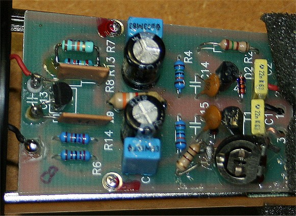 MCA SP-1 modified imp. converter board (TOP).