Ceramic C's, (X7R, Z5U, Y5V, but not NP0 types), have a LARGE and irregular temperature coefficient (they can "jump" in value) ! They can cause "popping" or cracking noises.
|
Component demands and why : |
Best use a sensitive low noise back electrets type with a very flat response, like the (omni) Panasonic WM-61A.
Supplier:
http://www.conrad.nl/ce/nl/product/335412/Elektreet-microfoonkap-EMY-63MP-
For this design, a simple modification to the mass-connection of the electrets capsule is necessary.
(see schematic diagram and modification of the elektret capsule).
See also
PCC uni directional floor microphone with balanced phantom feed line driver for a PCB and housing, and the use of an cardioids
type electret element like WM-55A103 (these cardioids are NOT usable for this L2array, it needs OMNI capsules ! ).
|
Do NOT use ceramic C's for C1-2 / C5-6. Use here FILM capacitors ! |
Best use low noise metal film resistors 1% if possible.
For stability reasons, a high quality CERMET trim pot should be used.
Avoid further problems with cracking noises, do not use Tantalum C's. Use wet electrolytic capacitors instead.
After completion and testing, glue all parts together and to the PCB for ruggedness.
Buy 10 pieces each for R12-13 , C1-2 , C5-6 and T1-2 .
Select matched pairs from them (at least less than 1% difference).
Use a digital universal meter with transistor test and capacitor test capabilities.
The exact value is NOT important, as long as you find two items very closely matched.
Also match T1 and T2 for equal DC gain (hfe) +- 5%, as this determines the OUTPUT impedances of these transistors, and THUS the XLR output balance.
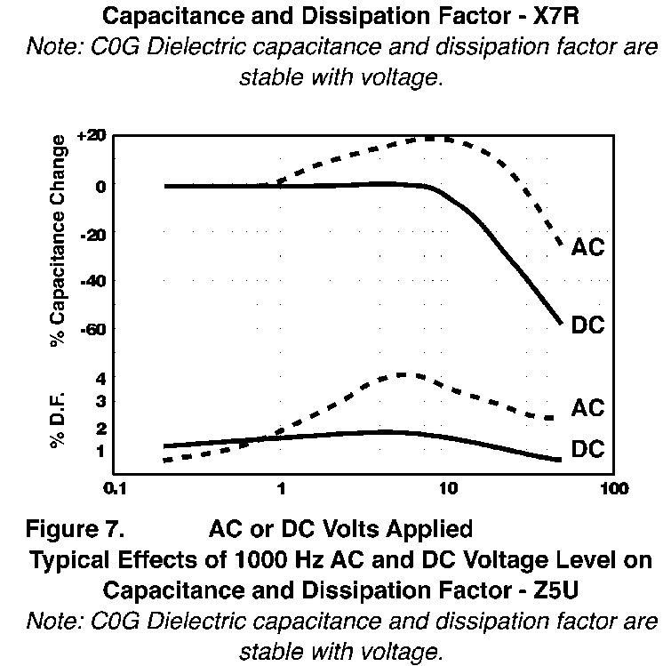
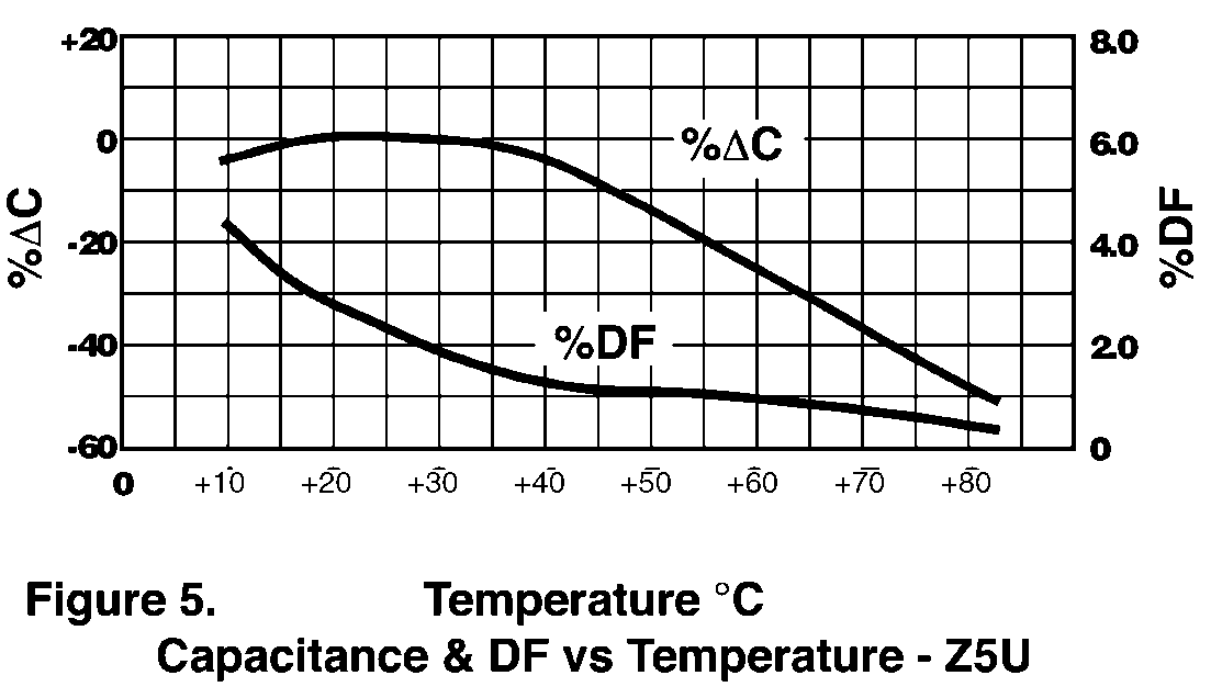
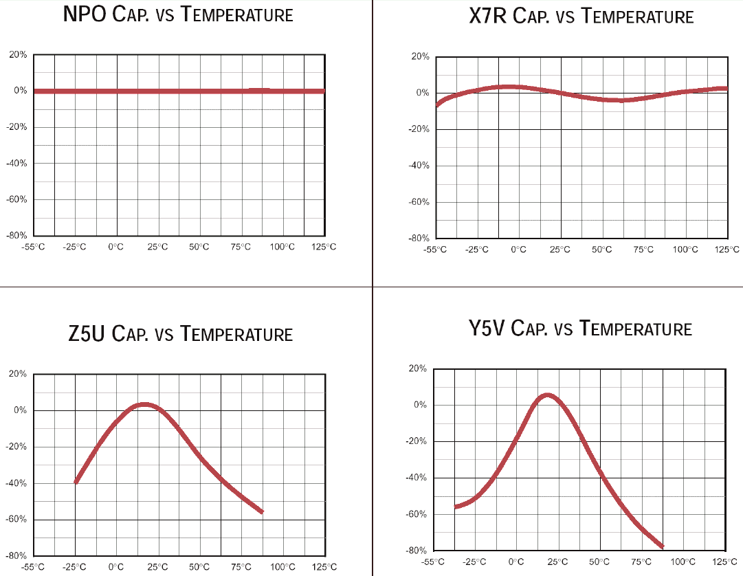
Ceramic capacitor data:
Ceramic C's, (X7R, Z5U, Y5V, but not NP0 types), have a LARGE and irregular temperature coefficient (they can "jump" in value) !
They can cause "popping" or cracking noises.
X7R, and espcially Z5U and Y5V type ceramic capacitors can also cause
distortion and IMD on applied audio signals !!
They change in capacitance value when their applied voltages change (DC more than 10V, and AC more than 0.5Vrms!).
So they modulate (distort) the applied audio voltages.