| << |
Proma 130040 cabinet :
Installing the tuner PCB in its cabinet.
Data on this page can be changed according testing of
the new prototype.
pa0nhc. Updated 20180309 |
General info.
If another cabinet than the suggested Proma is used, the
PCB could be installed at such a height, that its top surface is resting directly
onto the
underside of the BNC central pins.
The BNC pins and ground lugs then could be
soldered directly onto the PCB, avoiding wire connections.
The bottom half of the suggested Proma
cabinet contains one pair of slider rails for installation of the PCB. As the
BNCs cannot be installed low enough to make direct contact with the PCB, BNCs must be
connected using wires.
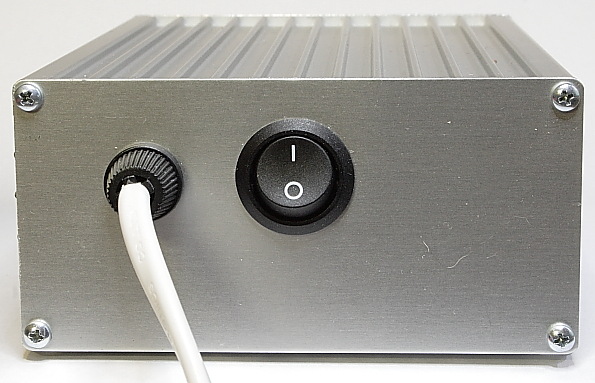
Use a good strain relief for the mains cable, as this protects you against a
short circuit between damaged mains cable conductors and the cabinet.
The eight self tapping screws are easier and safer to install, when a little
grease is put in their screw slots in the cabinet.
Glue the four plastic feet to the underside of the bottom part.
The amount of heath produced is small (abt. 3 W). No cooling measures have to be
taken, as in this PCB version, VR2 and R105/106 are cooled by
soldering in contact with the PCB.
Drilling ventilation holes is not needed.
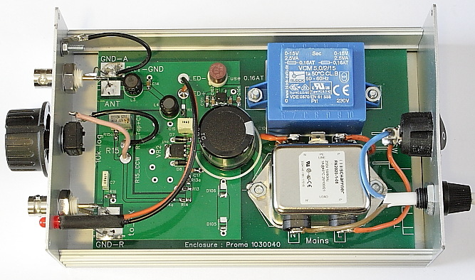
Installing the tuner PCB.
 Bend the NF mains filter solder lugs straight up.
Check for ample free space (>= 2mm) between :
1. Solder points on the bottom side of the PCB, and the bottom of the cabinet.
Especially at mains voltage carrying solder points.
2. Mains filter lugs and the side of the cabinet.
3. Mains switch lugs and mains filter.
For easier de-installation of the PCB towards the front
side, and the then needed unscrewing of the back plate, the wires connected to the mains filter
"N" and "L" should have ample length.
Tape the back panel drill template onto a panel, en
drill the holes.
Screw the back panel onto the bottom cabinet part.
Slide the PCB into the bottom part of the cabinet.
Connect the lower contact of the mains switch to mains filter
NF "L"..
Solder one wire of the 240V~ cable to the upper mains switch contact.
Solder the other wire of the 240V~ cable to the
mains filter NF "N".
 Tape the front drill template onto the other panel, en
drill the holes.
Tape the front drill template onto the other panel, en
drill the holes.
Screw the front panel onto the bottom cabinet part.
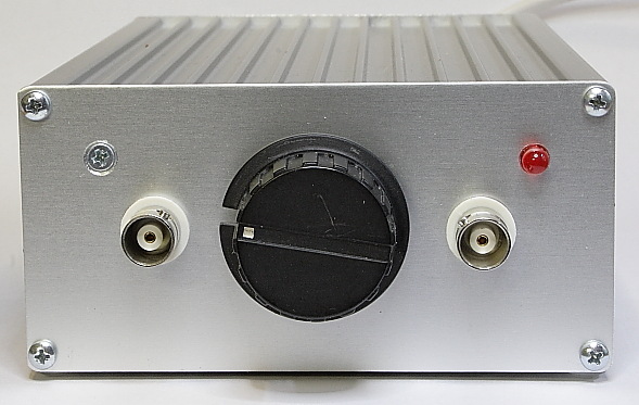
Install into the front plate :
- R15 with the tooth-ring between front plate and the plastic housing of R15, and the solder lugs directed to the left
- Both BNCs with their tooth-ring on the front side of the front plate, and their ground lugs directed towards their grounding surfaces on the
PCB.
- The LED. It should fit securely by pressing it in the 5 mm hole. Lock it with
some glue.
REM : the flat side on the
flange of the LED indicates "minus connection".
- An M3 counter sink "GND" screw with solder lug and nut on the inside
of the front plate..
The PCB mass planes will be connected to ONE
point at the inside of the front panel.
RF-noise currents induced to the outside of
the coax cable, and to the outside of the aluminum cabinet, will not intrude the
cabinet inside (Faraday cage). RF-noise currents on the outside of the cabinet
are thus separated from the cabinet inside and PCB signal lines.
The bottom half of the suggested Proma
cabinet contains one pair of slider rails for installation of the PCB. While
using this nice cabinet, the
BNCs cannot be installed low enough to make direct contact with the PCB, and the
BNCs must be
connected using wires.
 - If possible, solder the ground lugs of the BNCs directly onto the ground surface of the PCB.
else connect them with the short pieces of wire
coming from the PCB "GND" surfaces.
- Solder the wires from the PCB surfaces " ANT" and "TO_RX" short
to their BNC center pins
- Solder the R15 connections.
- Connect the LED.
- Connect the wire coming from "GND-A" to the ground lug at the front
panel.
Testing.
Caution : Do not touch any to mains voltage connected points.
Unplug the mains power.
Measure the insulation resistance between a mains filter MF connection and the
cabinet .
It MUST be infinite. If possible, test the insulation using a high voltage "Megger".
Connect a 270 Ohms 1W resistor (4x 68 Ohms 0.25W
in series) to "ANT", with a volt meter (200V
range) in parallel.
REM : After a few minutes operation, VR2 and its cooling surface
feel hot (60 C). This is normal.
Turn tuning potmeter R15 fully CCW.
Switch the unit on. The LED should light up. If not, check R17 connections.
Measure the output voltage on BNC "ANT". It should be abt. 14.0 Vdc.
Turn R15 fully CW.
Adjust R15b until the output voltage is 19.0 Vdc.
Remove the test resistor from "ANT".
The power supply is now unloaded.
Measure the bridge rectifier output voltage on the upper connection of D106.
It should not be higher than 35 Vdc, indicating
D105 and D106 are protecting C100, C16 and VR2 against over voltage in case of
disconnected antenna unit.
Both zener diodes will become hot.
Connect the antenna unit. If a short circuit in the coax cable
or in the antenna unit occurs, fuse "Z1" will blow, and needs replacement.
Measure the tuning voltage on R16 in the antenna
unit.
Turn R15 fully CCW. The tuning voltage should be not lower than 1.0V.
This voltage could differ, when the zener voltage of D5 differs from 13 V.
This voltage can be corrected by changing the output voltage from the tuner
unit. Then change the value of R14a. The change is 1V / kOhm.
Turn R15 fully CW. The tuning voltage should be
abt. 7.0 V.
This voltage can be corrected by changing the output voltage from the tuner
unit. Then change the setting of R15b. If needed, also change R15a.
Presuming the self inductance of L1 is 20 uH :
Turn R15 fully CCW.
Adjust C11 in the antenna unit for resonance on 3.48 MHz.
Turn R15 fully CW.
The antenna circuit should resonate around 3.82 MHz.
For a maximal possible tuning range, and a
maximal allowable varicap diode voltage of 18V :
Exchange potmeter R15 for 20 kOhms log, and exchange R15a for
180 kOhms.
The tuning range could further be enlarged,
by soldering an extra variacap diode pair BB814 on top of (in parallel to) D3.