| << |
Assembling the tuner PCB. |
Be
sure there is enough free space between the soldered connections and the bottom
of the aluminum cabinet.
After completing all soldering on the tuner PCB, on
the underside of the PCB, every
through-hole solder connection MUST be cut down. As an extra safety measure, you could glue or tape a piece of polyester sheet onto the cabinet
bottom surface.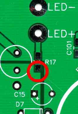
|
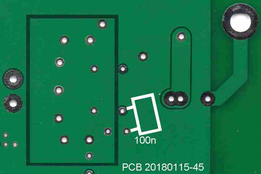
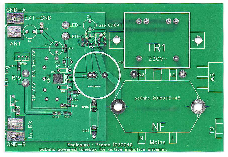
Changes for PCB
2010115-45 (see pictures) : |
Solder components in this order :
- Resistors
- Capacitors (except C100)
Keep the specified types in mind (FILM / Elco / Ceramic) !
- Chokes.
Use a tip temperature, at which solder time is short, but the resin does not
burn brown or black.
For thick pins and wires, use a higher tip temperature to keep solder time
short.
For soldering heavier contacts like the cooling pin of VR1, use a THICK bit
with wide tip.
First put a little electronic soldering fluid onto the to be soldered pad for
easier tinning (violin resin in alcohol).
Try to minimize soldering time to under 10sec.
Let cool down well after every point soldered.
First take NOW anti-static precautions.
|
|
- Diodes D105 and D106. They are cooled via their soldering.
- Solder one pin of VR1.
- Correct the position/location of it.
- Solder the other pin.
- Solder the cooling tab of VR1 onto its PCB cooling surface.
- Screw with the head from the bottom up, and solder
- Transformer TR1
- Mains filter NF (see "safety").
- At the grounded screw hole (keft
one) of
filter NF, solder the rim of
the filter casing to that screw hole (see PCB tracks).
- Lock screws and nuts with
glue or LockTight..
- Solder C100 well in mechanical contact with the PCB surface. Fix it to the PCB with a bit of glue.
REM : A "snap-in" type elco will NOT fit into these holes.
Also solder :
- Two insulated wires for pot meter R15 ("M+CW" and "CCW").
- Two insulated wires for the LED.
- One insulated wire at the PCB "EXT_GND" for connection to the front
panel GND.
- Four blank wires for the BNC center pins and ground lugs.
Keep their length long, they will be cut to length after installation of the
PCB.