Download
|
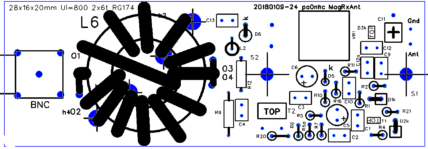
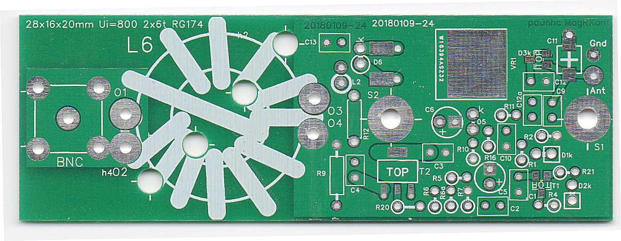
Assembling the antenna PCB. |
FET T1, and varicap D3 are static sensitive. Take precautions.
Also temporarily connect
"Ant" to a ground connection, but remove this after connecting the antenna coil L1.
All components are situated on the top copper.
Most resistors are mounted
vertically to save space.
Install vertically placed resistors with their bended long wire in the direction
like shown in the picture. It makes measuring voltages at points of interest is easier.
Solder :
- Resistors
- Diodes
- Capacitors
- L2
- BNC
Use a soldering iron with thick tip,
and a temperature of maximal 260 C, to prevent damage to semiconductors.
Solder not longer than 10 sec.
Let cool down after every soldering.
- Solder one pin of T2.
- Check that its position is correct.
- Solder the other pin.
- Solder the wide tab to the PCB.
- Solder one pin of VR1.
- Check that its position is correct.
- Solder the other pins.
- Solder the wide tab to the PCB.
- Solder D3
- Solder T1 as last.
Fair-Rite
29mm mix #31
(26318012002), available at arrow.com Wind L6 with (at least) 2x 6 turns THIN
coax (RG174 or RG316). Rem : some overlapping of turns on the same winding half are allowed, as long as the space to winding begin or end is large enough to keep coupling capacitance small. - Fix the coax ends onto the ferrite
core
using Ty-Wraps (R). - Cut the coax ends to length, and make short connecting pigtails. |
- Fix the completed choke onto the PCB, using two
Tywraps(R) running through the four PCB holes.
- Quickly solder the coax ends to the PCB. Observe ground connection locations.
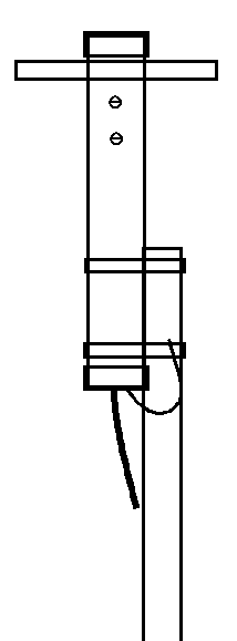
REM :
When installed inside a small enclosure like a piece of PVC pipe, and power is always supplied to the antenna unit, the
little heath produced by VR1 and T1 will prevent condensation.
Grounding.
The antenna PCB has two 3.2mm screw holes with a distance of 32.8 mm. They are
connected to the PCB ground planes.
Use two M3 10mm long metal separation bushes to install the PCB into its 50mm
dia.
housing.
Screw an insulated thick wire under the lowest screw. This is your
grounding wire for connection to the grounded mast.
|
REM : do NOT ground the coax-mantle nor the BNC plug. Connect the external noise free ground only to the PCB hole S1 or S2 (or at the outside of the PVC housing pipe, under the screws at the metal distance bolts). |
You could use stainless steel hose clamps or muffler clamps to fasten the antenna to the mast.
Try to keep as much distance as practical between the ferrite antenna and metal
objects.
For instance use a long PVC pipe as antenna housing, with
the antenna PCB positioned free, several decimeters above a grounded metal mast.